5000KIT | 5000KIT AUTOMATION SET 69
MOUNTING
A
W
C
B
α
E
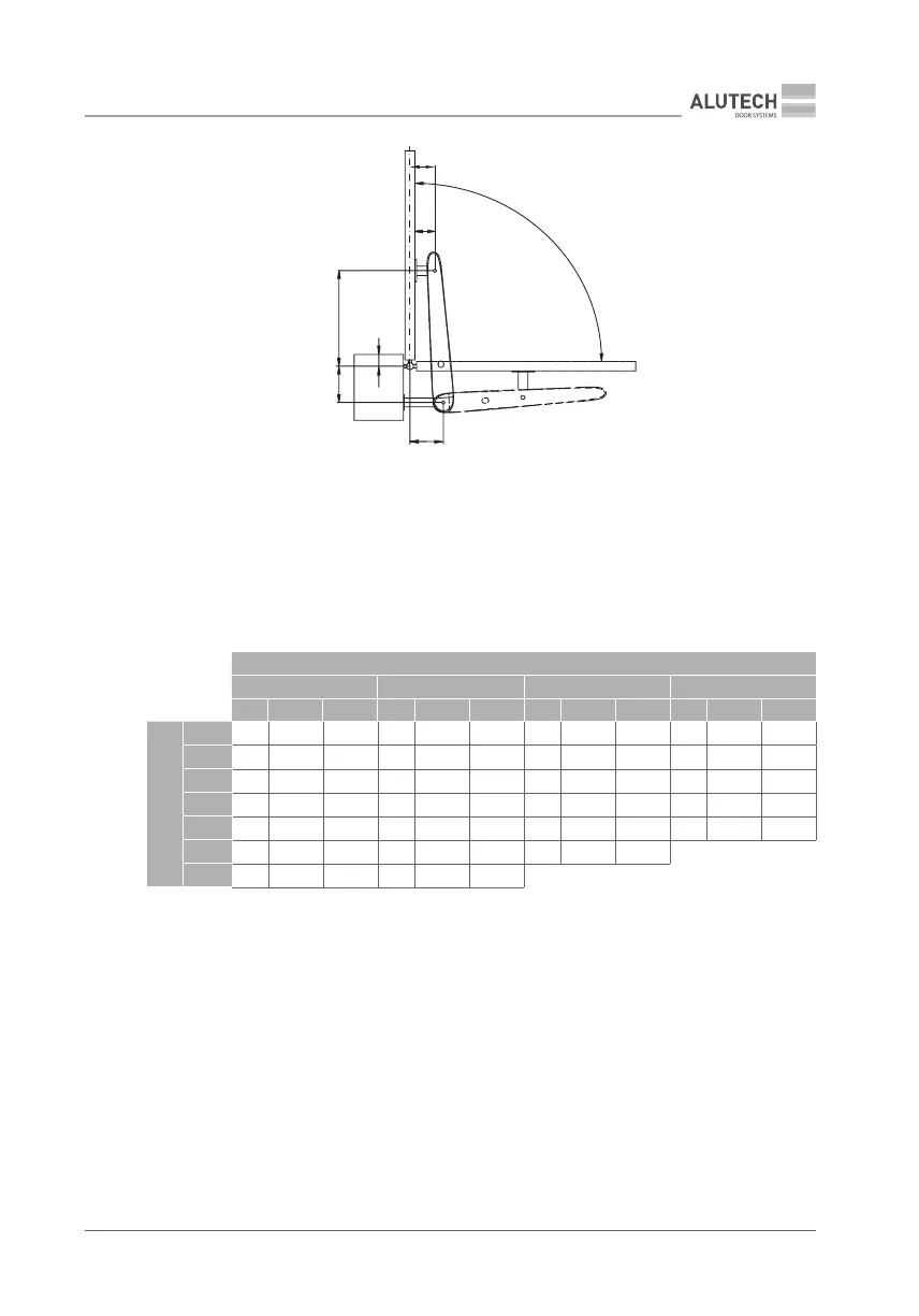
Figure 5. Mounting diagram for a gate opening outwards
and — dimension between the leaf hinge axis (leaf rotation centre)
and the axis for mounting a drive on its rear tting; C — dimension between the leaf hinge axis and a post edge;
W — dimension between the leaf hinge axis and the axis for mounting a drive on its front tting;
E — dimension between a leaf edge and the axis for mounting a drive on its front tting (g.8),
minimumdimension Е = 134mm; α — leaf opening angle;
X — dimension between the leaf hinge axis (leaf rotation centre) and
the axis for mounting a drive on its front tting.
A MM
170 190 210 230
α° C (mm) W (mm) α° C (mm) W (mm) α° C (mm) W (mm) α° C (mm) W (mm)
B MM
170
90 − 40 750 95 − 40 735 100 − 40 715 100 − 40 725
170
90 − 20 750 95 − 20 735 100 − 20 715 100 − 20 725
170
90 0 750 95 0 735 100 0 715 100 0 725
190
90 20 750 95 20 735 100 20 735 95 20 725
210
90 40 750 95 40 735 95 40 745 90 40 725
230
90 60 750 95 60 760 90 60 740
250
90 80 760 90 80 760
Pay attention to the following:
• the A and B dimensions must be almost equal, while the travel length S should be maximum
to ensure constant speed and pushing (pulling) force when a leaf is moving, i.e., a smoother
motion of the leaf.
• the sum of the A and B values should be almost equal to the useful drive travel required
toopen a leaf to the angle α = 90 º.
• pay special attention to the C dimension to avoid the drive hitting a post edge.
• The condition B > X should be observed. Avoid the drive hitting a gate post.
• when a gate is closed or open, the drive should be at an angle to a leaf (fig. 6).
• note that, for a gate opening outwards, the drive-through width may be reduced due to the
drives overhanging into the drive-through area (fig. 7).
Table 5