5000KIT | 5000KIT AUTOMATION SET 67
MOUNTING
RG58
2×1
4×0,5
4×1,5
4×1,5
2×0,5
3×1,5
3
5
4 6
1 2
6
7
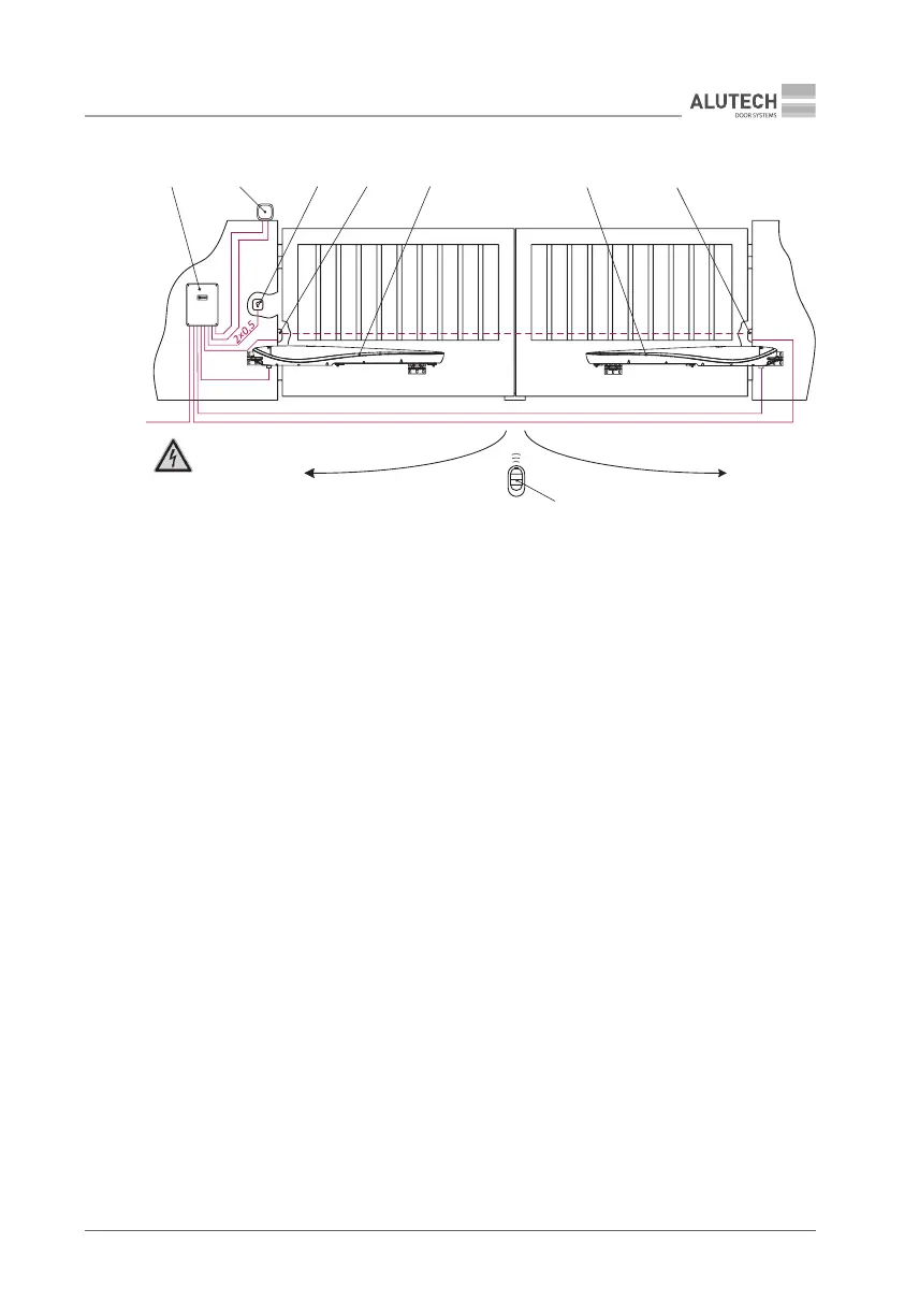
Figure 3. A typical automation diagram for a double-leaf swinging gate
(opening inwards)
1 — rst drive (drive on the leaf that opens rst); 2 — second drive; 3 — control unit;
4 — key-switch or a numeric pad on the exterior; 5 — a lamp with a built-in antenna;
6 — photocells on a post (or a wall) on the exterior. It is also recommended to install posts
with photocells to ensure safety in the gate opening area; 7 — remote control
4. MOUNTING
Y
When mounting a drive, please, make sure to position it properly and align carefully relative
to the gate.
Please, make sure that the mounting dimensions and angles match the design of the gate,
leaves, and hinges.
Fasteners (bolts, plugs, anchors) required to install a drive should ensure reliable and rigid
mounting to prevent loosening during operation. When installing, please, make sure that the
drives are not too close to a post edge.
The optimal mounting height for a drive is halfway up the height of a leaf. Do not install the drive
close to the ground surface (the minimum distance from the ground level should be 300 mm).
The drive should be positioned horizontally.
The location, where a tting is attached to a leaf, should be solid enough to ensure an ecient
load distribution across a leaf structure.
Prior to welding, please, protect the drive and gate elements from welding sparks and spatter.
After the mounting has been completed, please, remove the leftovers of welding and tting
works from the drive and gate ttings. Where welding has taken place, make sure to protect the
welding locations from corrosion.
Mount the control unit with its cable ducts facing down to avoid water ingress.