Operating Instructions (18-0015) AM-48 Test Set
0015-S077-20
Ameritec
PERSONAL TRANSMISSION TEST SET
MODEL AM-48
SEND MEASURE FILTER
ON
ABS
REL
SEND
ON/
OFF
∇
∇
∇
DAMP
∇
∇
OFF
SEL
900Ω
600Ω
∇
∇
∇
SEL
∇
∇
SEL
∇
∇
3K C-MSG
15K PROG
QUIET 1004 VAR
PAR
L/F
PAR3 TONE SWEEP
NOISE NOISE S/N
HOLD
TONE
IMPLS ØJTR JTR TRANS
∇
∆
•
•
MON RCV
MON SND
TALK
∇
TERM
∇
BRDG
∇
∇
•
4W
•
TONE
PULSE
ON HK
∇
∇
•
MF
DTMF
SHIFT
ETR/NEXT
ETR/PREV
CANCEL
STOPSTART
4W/2W
SND
4W
RCV
+
/
-
∇
∇
∇
∇
∇
2W
4W REV
MIC
VOL
PRT EAR
DC
9V
∇
∇
∇
•
SF SKP
NOR
X TONE
∇
RCL/STO
∇
∇
•
PRINT
∇
21 A3
54 B6
87 C9
0
*
D#
Set 3 TONE* or PAR
*
SLOPE for AM-48E
<SEND>
SWITCH SETUP
<SHIFT>
DBM
3K C-MSG
15K PROG
QUIET 1004 VAR
PAR
L/F
PAR3 TONE SWEEP
NOISE NOISE S/N
HOLD
TONE
IMPLS ØJTR JTR TRANS
∇
∆
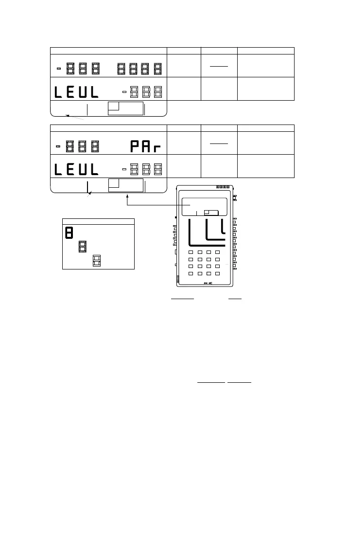
PAR darkened
•
•
PAR DISPLAYS
NAME
ACCEPTABLE VALUES
NOTES
PEAK-TO-AVERAGE
RATIO
"PAR"
0.0 to -40.0* dBm
Send Level of Peak-to-Average
Ratio Waveform.
*
PAR waveform level has range 0.0
to -40.0 dBm (not 10.0 to -50 dBm,
as with other tones).
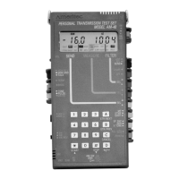
LEVEL
"LEVL"
DISPLAY CHARACTER CODE
Parameter Name (Fixed)
Key from which Programmed
See ¶7.8 for general procedure to set new parameter values.
User-Entered Value
Tone is Sent
DBM
HZ
3K C-MSG
15K PROG
QUIET 1004 VAR
PAR
L/F
PAR3 TONE SWEEP
NOISE NOISE S/N
HOLD
TONE
IMPLS ØJTR JTR TRANS
∇
∆
3 TONE (SLOPE FOR AM-48E) darkened
DBM
•
•
•
SLOPE DISPLAYS
NAME
ACCEPTABLE VALUES
NOTES
SLOPE
TONES
10.0 to -50.0 dBm
Send Level and Frequency (404,
404 Hz, 1004 Hz, 2004 Hz, 3004 Hz for AM-48E
1004, 2804 Hz* for 5 sec., cyclical).
Set level for all tones sent (except
dialed tones).
Level for all tones sent (except
dialed tones).
LEVEL
"LEVL"
DBM
*
Figure 7-3. Parameter Settings from 3-TONE Slope and PAR SEND Displays
7.17 Send Variable Sweep
See ¶5.7 for an example of setting the parameter values for this SEND
mode. Figure 5-7 shows the displays with the default parameter
settings. Figure 7-4 shows the general displays.
1. See Figure 7-4. Set switches per the SWITCH SETUP
illustration,
and set the SEND cursor per the menu illustration.
2. See ¶7.8. Set the parameter values for the desired sweep per the
acceptable values and notes in Figure 7-4.
3. The new parameter values are stored in volatile memory.