AM-48 Test Set (18-0015) Operating Instructions
0015-S07
7-
5. Go to “JITR” display and read the peak-to-peak phase jitter.
Ameritec
PERSONAL TRANSMISSION TEST SET
MODEL AM-48
SEND MEASURE FILTER
ON
ABS
REL
SEND
ON/
OFF
∇
∇
∇
DAMP
∇
∇
OFF
SEL
900Ω
600Ω
∇
∇
∇
SEL
∇
∇
SEL
∇
∇
3K C-MSG
15K PROG
QUIET 1004 VAR
PAR
L/F
PAR3 TONE SWEEP
NOISE NOISE S/N
HOLD
TONE
IMPLS ØJTR JTR TRANS
∇
∆
•
•
MON RCV
MON SND
TALK
∇
TERM
∇
BRDG
∇
∇
•
4W
•
TONE
PULSE
ON HK
∇
∇
•
MF
DTMF
SHIFT
ETR/NEXT
ETR/PREV
CANCEL
STOPSTART
4W/2W
SND
4W
RCV
+
/
-
∇
∇
∇
∇
∇
2W
4W REV
MIC
VOL
PRT EAR
DC
9V
∇
∇
∇
•
SF SKP
NOR
X TONE
∇
RCL/STO
∇
∇
•
PRINT
∇
21 A3
54 B6
87 C9
0
*
D#
Set Ø JTR or
<ABS>
SWITCH SETUP
<SHIFT>
HZ
HZ
3K C-MSG
15K PROG
QUIET 1004 VAR
PAR
L/F
PAR3 TONE SWEEP
NOISE NOISE S/N
HOLD
TONE
IMPLS ØJTR JTR TRANS
∇
∆
See Note below
Ø JTR darkened
•
•
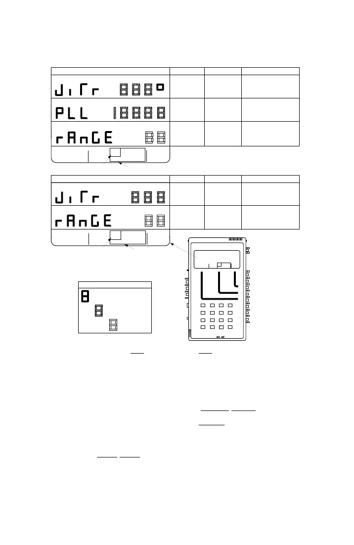
PHASE JITTER DISPLAYS
NAME
RANGE
NOTES
PHASE
JITTER
"JITR°"
AMPLITUDE
JITTER
"JITR°"
PHASE LOCKED
LOOP FREQUENCY
"PLL"
FREQUENCY
BANDWIDTH
"RANGE"
FREQUENCY
BANDWIDTH
"RANGE"
0.0 to 25.0 degrees
0.0 to 25.0 percent
0.0 to 1999.9 Hz
Peak-to-peak phase jitter displayed.
Peak-to-peak amplitude jitter
displayed.
Phase-locked-loop frequency
displayed.
to 300 Hz. Press [2] for 20 Hz to
to 300 Hz.
Select bandwidth: Press [4] for 4 Hz
4 or 20 Hz
to 300 Hz. Press [2] for 20 Hz to
to 300 Hz.
Select bandwidth: Press [4] for 4 Hz
4 or 20 Hz
DISPLAY CHARACTER CODE
Parameter Name (Fixed)
Key from which Programmed
See ¶7.8 for general procedure to set new parameter values.
User-Entered Value
Tone is Sent
HZ
3K C-MSG
15K PROG
QUIET 1004 VAR
PAR
L/F
PAR3 TONE SWEEP
NOISE NOISE S/N
HOLD
TONE
IMPLS ØJTR JTR TRANS
∇
∆
∇
∆
∇
∆
•
•
AMPLITUDE JITTER DISPLAYS
NAME
RANGE
NOTES
See Note below
JTR darkened
A holding tone (990 to 1030 Hz) must be present for the
measurements to be valid. HOLD TONE darkened
indicates presence of valid holding tone.
NOTE
JTR
Figure 7-8. Phase JTR and Amplitude JTR MEASURE Displays
7.33 Measure Amplitude Jitter
1. See ¶8.11 for explanation of Amplitude Jitter measurement.
2. See Figure 7-8. Set switches per the SWITCH SETUP
illustration,
and set the MEASURE cursor per the bottom menu illustration
(AMPLITUDE JITTER DISPLAYS).
3. Be sure HOLD TONE
cursor is darkened, indicating a valid
holding tone is being received.
 Loading...