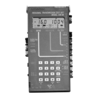
Unit Description (18-0015) AM-48 Test Set
0015-S033-2
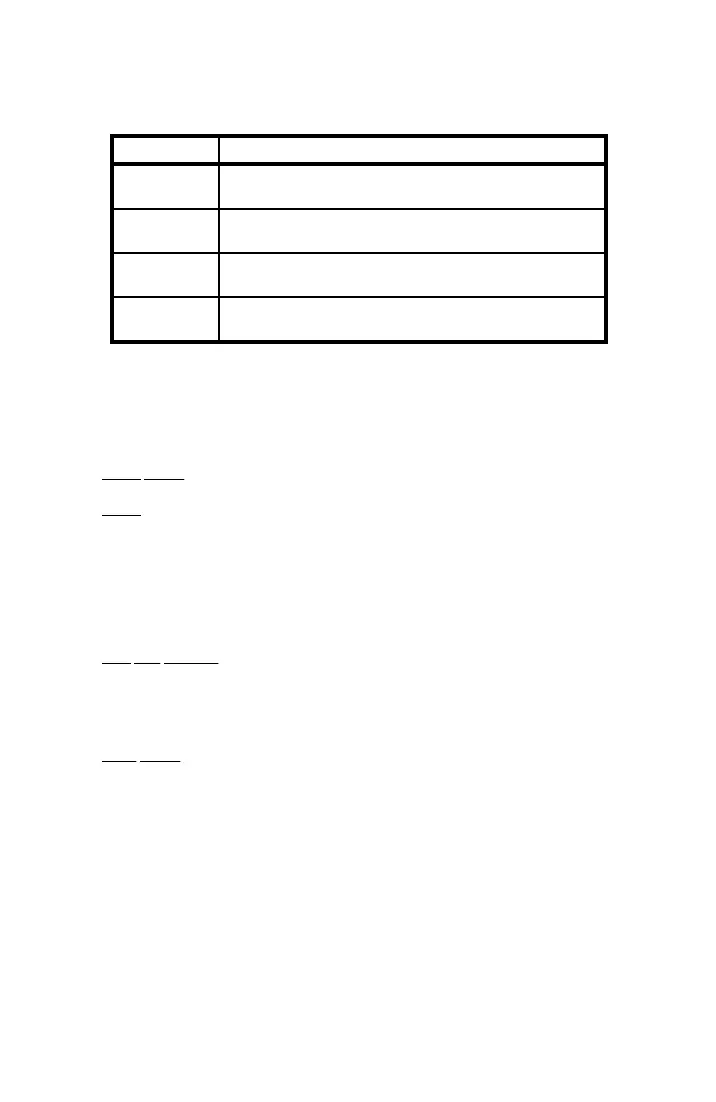
Table 3-1. Front Panel/Switches Color Coding
Color Description
Black & Blue Line controls. Associated with configuring the AM-48 for the
type of line to be measured.
Yellow Send controls. Associated with selecting the desired signal
generator (send) function and controlling the signal generator.
Red/Pink Measure controls. Associated with selecting the desired
measurement function and measurement characteristics.
Orange On menus: all noise-weighting filters and the measurements
that require a noise-weighting filter.
3.3 Component Location
Figure 3-1 shows the location of components on the front panel and
sides.
Front Panel . Liquid crystal display and keyboard.
Sides . There are two (2) slide switches on the left side and a total of
12 color-coded rocker switches along the left and right sides. The
rocker switches are protected from abuse by integral "ribs" molded
into the case. A thumb wheel speaker volume control and slots for
the microphone are also located on the left side.
Top and Bottom . The slots at the top are for the speaker.
Connectors for the transmission line, AC adapter, earphone, and
printer are located along the bottom, as illustrated in Figure 3-2.
Rear Panel . You may access the battery compartment through a slide
door in the rear panel. See ¶4.2 and 4.3 for details.