Operating Instructions (18-0015) AM-48 Test Set
0015-S077-6
6. At the bottom of some figures, an alternate display(s) is
illustrated, e.g., “OVER” or “UNDR”, which may be displayed to
call attention to an out-of-tolerance condition.
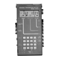
7.5 General Switch Setup
See ¶3.5 for a summary of the use of each switch. Refer to Figure
3-5 for switch identification number (see ¶3.2). Follow the
guidelines below for proper switch setup.
1. Make connections and set Switches 10, 11, and 13 per the line
interface. See ¶6.3 thru 6.5 for details.
2. Connect and turn on power with Switch 1 per Section 4.
3. Switch 2, Display Select, determines what appears on the
display. Set Switch 2 to the desired position:
a) <ABS> to view MEASURE display (see ¶7.22 for use of
<REL> position).
b) <SEND> to view SEND display
4. Use Switches 5 and 6 to set the display cursor to the desired
SEND and MEASURE modes, and Switch 4 to select a noise-
weighting filter, if required (see Table 7-5).
5. Set Switch 7 to <SHIFT> to enable auxiliary keyboard functions
to:
a) Scroll through multiple displays
b) Use keyboard to change a parameter value
c) Send momentary user-programmed tone from
keyboard in
QUIET mode
d) Do Store/Recall
e) Run a transient test
f) Do auto calibrate
Leave Switch 7 in <SHIFT> except when dialing.