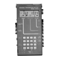
AM-48 Test Set (18-0015) Operating Instructions
0015-S07
7-
b) Cross-hatched : These characters represent values that
are
variable but cannot be changed by the user from
the display in which they are shown. In the SEND
modes these indicate the level and frequency being
sent; in the MEASURE mode, they give the measured
values.
c)
Plain : These characters represent parameter values
that are
variable and can be changed by the user from
the display in which they are shown.
2. Next to each display is a
table of information and instructions
which apply to the adjacent display. The middle column of the
table gives the range of acceptable values to enter for a variable
parameter or the range of values that can be measured.
3. The SEND or MEASURE
cursor setting is shown darkened on the
menu just as it appears at the bottom of the AM-48 display.
There are always three (3) cursors in view, although only one (1)
is shown in each of the figures. The positions of the other two
(2) cursors will depend upon the test configuration and setup.
4. The
switch settings are indicated next to the location of the
switches in the illustration of the AM-48 at the bottom of the
figure. Only the necessary switch settings for the test under
consideration are shown. Set the other switches as appropriate,
according to the test configuration and setup.
5. The
notes on the left at the bottom of the figures relate to the
displays. The notes on the right relate to the switches and
keyboard.