Measurements (18-0015) AM-48 Test Set
0015-S088-6
8.7 P/AR Measurements
Definition of P/AR . P/AR (Peak to Average Ratio) measurements
are made by applying a special 16 tone (PAR) signal at the distant
end of the line under test. At the near end, the AM-48
simultaneously measures the peak value and average value of the
received test signal.
The ratio of the Peak value to the Average value
of the transmitted signal is arbitrarily assigned a value of 100 .
If the transmission channel were non-dispersive, the received Peak-
to-Average Ratio would also have a value of 100. A typical
telephone channel, however, causes smearing or Intersymbol
Interference, and a value of other than 100 is observed.
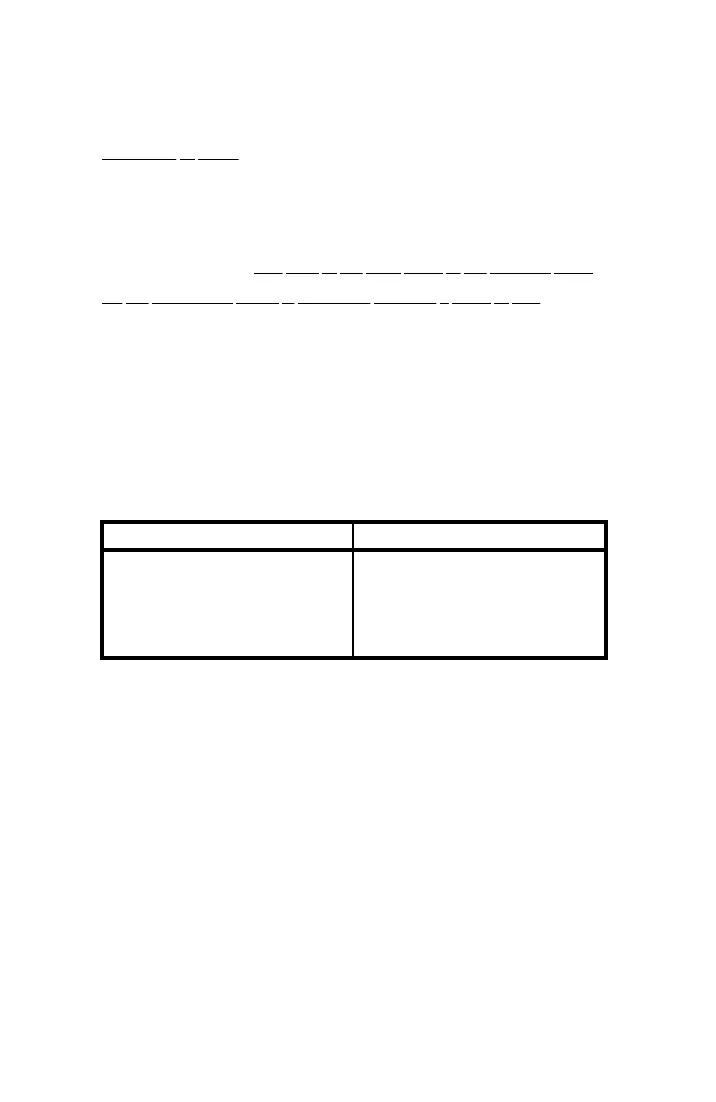
Table 8-1 shows some typical values that might be used to judge the
acceptability of a telephone line to reliably transmit data.
Table 8-1. P/AR Requirements of Telephone Lines
CIRCUIT CONDITIONING TYPICAL P/AR VALUES
BASIC CHANNEL
C1
C2
C4
C5
45
48
78
87
95
EXAMPLE: If a modem requires a C2 conditioned line and a P/AR
of 50 is measured, the line is likely to encounter transmission
problems. On the other hand, if a P/AR of 78 is measured,
InterSymbol Interference will not present problems.
The P/AR value of the received (distorted) signal is made according
to the following formula:
P/AR = 100* (K P/Afw –1)
Where: P = peak voltage of received signal
Afw = full-wave average of the received signal
K = a constant