Connection & Configuration (18-0015) AM-48 Test Set
0015-S066-6
AM-48 Interface with Line Connections . The position of Switch 10
(Figure 3-5) determines the connection of the AM-48 internal
circuitry to the 2-wire or 4-wire lines. The connections for the
different settings of Switch 10 are listed below:
<2W> Connects the internal measurement circuitry to the
signal generator across the 2-wire line at the <SND>
jack. The signal generator source impedance 600Ω or
900Ω (determined by Switch 11) terminates the line in
all signal generator modes except QUIET. In QUIET
mode, the line will be terminated only if Switch 13 is
set to <TERM>. Note that the
< RCV > jack is not used
to connect to 2-wire lines .
<4W> Connects the internal measurement circuitry to the
<RCV> pair, and the internal signal generator to the
<SND> pair.
<4W REV> Send and receive pairs (as defined above) are reversed.
See ¶6.4 and 6.5 for details about line termination impedance.
AM-48 is Polarity Insensitive . It does not matter which way the Send
pair or Receive pair of contacts are connected. The Send <SND> T
and R can be interchanged without affecting the measurement. The
Receive <RCV> T1 and R1 may also be switched without changing
the measurement.
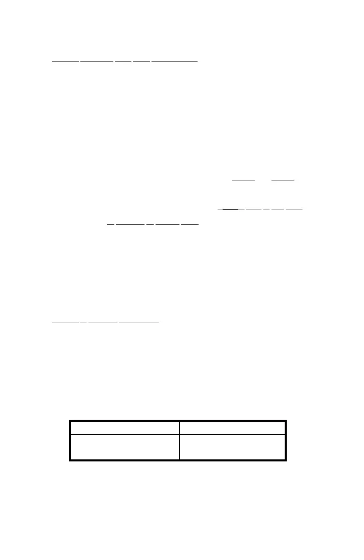
For example, in Figure 5-1, which shows the loopback connections
for self-test, the connections could be changed as indicated below:
Figure 5-1 Connections Alternate Connections
RED (R) to BLACK (R1)
GREEN (T) to YELLOW (T1)
RED (R) to YELLOW (T1)
GREEN (T) to BLACK (R1)