4-2 | Thermox TM2000 Oxygen Analyzer
Areas of the Control Unit
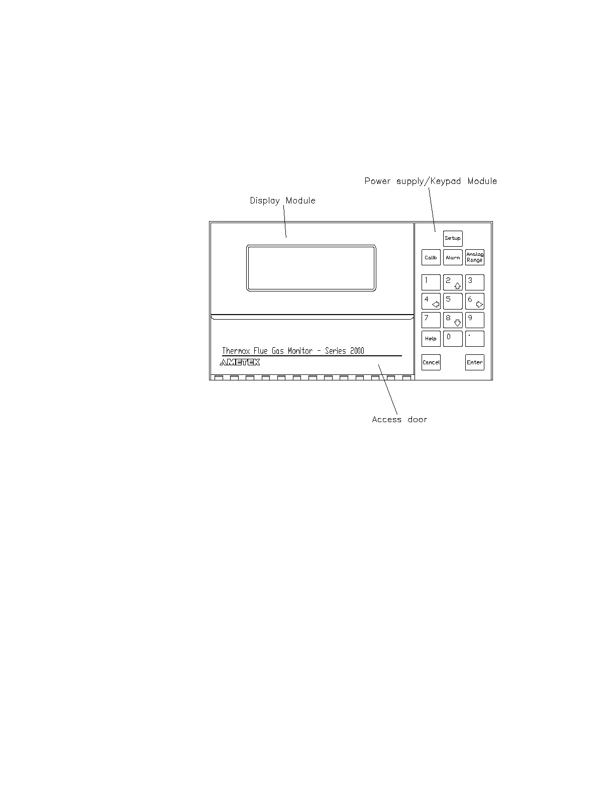
Figure 4-1 shows the various areas of the control unit including the loca-
tions of the power supply/keypad module and display module. The con-
trol unit is operated by pressing keys on the keypad.
Figure 4-1.
Front view of Series
2000 control unit.
Password Restrictions
For menu options to change system settings in which a password is
required, you must first enter the password to access that menu’s func-
tions. See the Setup Key section of this chapter for help on how to create a
system password.
Control Unit Display
The main control unit display allows viewing of different types of infor-
mation. You define which information to place on the first three lines of
the display by using the Display option from the Setup Key. Note that you
can also use the Display menu option to place your own text messages
on one or more of the first three lines. The last display line is reserved for
system and error messages.
 Loading...