Anderson Group Self-loading Bale Carrier TSR-3450 – Operator's Manual 43
5 Operation
5.1 Controls
The hydraulic control levers located on the
side of the bale carrier must never be used to
manoeuvre the carrier. They are only used for
diagnostics and troubleshooting.
See chapter 7 Troubleshooting to find out
which component is activated by each of
these levers.
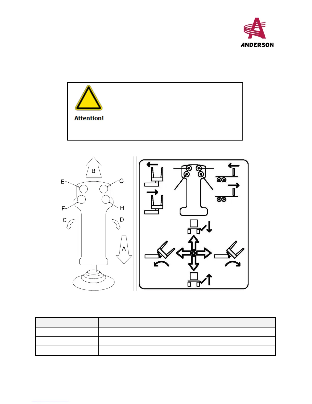
The following figure represents the control lever and the functions associated with each button.
Figure 20- Control Lever
Table 7- Actions Associated with the Buttons
Button/Action Manoeuvre
A Raise the loading arm
B Lower the loading arm
C Pivot the grabber towards the bale carrier
 Loading...