Chapter 6 — Removal and Replacement Procedures 6-2 Power Meter Disassembly
ML248xx, ML249xA MM PN: 13000-00164 Rev. K 6-7
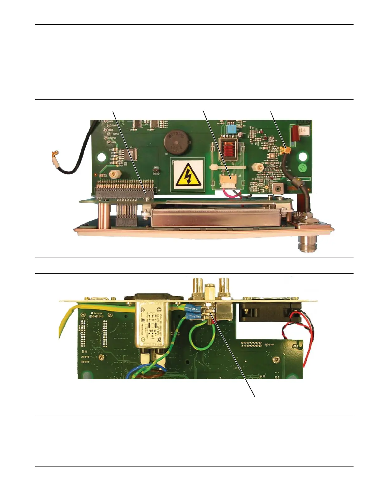
Front Panel Removal
The front panel assembly is removed from the control PCB. See Figure 6-8 and Figure 6-9.
1. Disconnect the LCD backlight cable from J8 on the control PCB.
2. Disconnect the RF calibrator cable assembly from J2 on the control PCB (not applicable for ML249xA).
3. Remove the front panel PCB from the control PCB, by gently prying the two PCBs apart at the 50-way
PCB-PCB connector at J4 on the control PCB.
4. Undo the locking nuts on the rear panel grounding stud to release the ground cable that connects to the
front panel assembly. The front panel assembly is now free.
Figure 6-8. Front Panel Removal
Figure 6-9. Front Panel Ground Removal
Earth Ground Connections
at Rear Panel Ground Stud