ML248xA / ML249xA Common Procedures
5-10 13000-00162
September 2005
Channel
Understanding and Setting Up the Channels
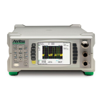
The ML248xA / ML249xA has either single or dual sensor inputs, two channels, two
modes, and two measurement display options, and before explaining how these are set up,
it is first important to ensure that the meanings and uses are fully understood.
Sensor Inputs
The sensor inputs are the physical connector(s) on the front panel to which the sensors
are attached. The ML2488A and ML2496A have two sensor inputs, labelled A and B, and
the ML2487A and ML2495A have one.
Channels
Both the ML248xA and the ML249xA have two display channels; 1 and 2, each of which
may be configured to measure a signal from either a CW or pulsed/modulated source, and
each of which may display the results in either a profile (graphical) or readout form. The
channels can also be configured for any of the available sensor inputs. To allow each
channel to be set up as required, the power meter employs the concept of the “active
channel”. The active channel can be changed at any time by pressing the Ch1/Ch2 hard
key.
Modes
There are two modes available; “Pulsed/Modulated” and Continuous Wave (“CW”), and
both of the channels can be set up for either mode.
Mode Definition
Pulsed/Modulated
Select this mode to measure pulsed or modulated
signals. This selects the high-speed data acquisition
system to measure the signal. The measurement is
made on data captured over a specified time period.
This time period can either be set by the user in the
gate settings, for example for TDMA or Radar
measurements, or can be left at the default setting for
applications such as CDMA.
CW Measurements are made continuously and displayed at
a rate determined by the averaging parameters and
signal level.
 Loading...
