3-10 1 GHz Calibrator VSWR Verification Chapter 3 — Performance Verification
3-20 PN: 13000-00164 Rev. K ML248xx, ML249xA MM
12. Power off the N432A.
13. Attach the 8478B power sensor to the sensor cable.
14. Do not connect the power sensor to any source.
15. Power on the N432A.
16. Allow the N432A to zero the power sensor.
17. After zeroing is complete, attach the power sensor to the S820E or equivalent VNA.
18. Measure the VSWR at 1 GHz for each of the 4 resistance settings and record below:
VSWR
100
= ______________
VSWR
200
= ______________
VSWR
300
= ______________
VSWR
400
= ______________
19. Using the VSWR values from Step 12 calculate the reflection coefficient, also known as Gamma (Γ) for
each of the resistance values, using the following formula:
Γ
100
= ______________ (should be a number near 0.33)
Γ
200
= ______________ (should be a number near 0)
Γ
300
= ______________ (should be a number near 0.2)
Γ
400
= ______________ (should be a number near 0.33)
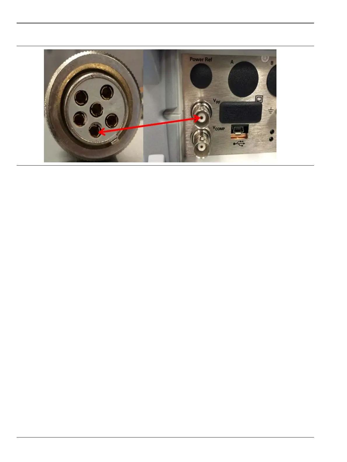
Figure 3-8. 100, 200, 300 and 400 Ohm Bridge Resistance Measurement
Γ
VSWR 1–()
VSWR 1+()
---------------------------------=
 Loading...


