Chapter 3 — Performance Verification 3-10 1 GHz Calibrator VSWR Verification
ML248xx, ML249xA MM PN: 13000-00164 Rev. K 3-21
20. For each of the resistance settings, connect the 8478B to the RF Calibrator of the DUT,
21. On the N432A, toggle the front panel Display button so that menu 2 of 2 is displayed.
22. Set the N432A to Display Voltages.
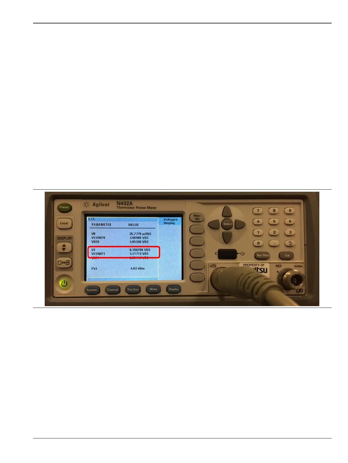
23. Press the “Voltages Display” button.
24. Note the measured values “V
1
” and “V
comp1”
as shown in Figure 3-9.
25. Change the N432A Bridge Resistance to 100 ohms as described in steps 5 and 6.
26. Ensure the RF Calibrator on the DUT is turned off.
27. Record the V
1
and V
comp1
values shown on the N432A into Table 3-5 as V
1
off and V
comp1
off.
28. Turn on the RF Calibrator on the DUT and allow the measurements to settle for approximately 10
seconds.
29. Record the V
1
and V
comp1
values on the N432A into Table 3-5, for V
1
on and V
comp1
on.
30. Turn off the RF Calibrator on the DUT.
31. When switching the RF Calibrator between On/Off and Off/On, allow the readings to settle for
approximately 10 seconds before recording the results.
32. Repeat step 25 through 31 with the N432A Bridge Resistance set to 200, 300 and 400 ohms.
Figure 3-9. V
1
and V
COMP1
Values Shown on the N432A
 Loading...


