13000-00162 11-1
September 2005
Chapter 11. WLAN Setup and Measurement
Setting Up the Power Meter for WLAN Measurements
Follow the procedure below to set up the ML248xA / ML249xA to perform WLAN
measurement.
Note: The “WLAN” options in the [Preset] dialog can also be used to automatically
configure the unit for WLAN measurement. Press the Preset hard key and then use the
arrow keys to select option 9, 10, or 11.
802.11b, a, and g
1. Perform calibration
Connect the sensor in use to the input on the front panel.
Connect the RF port of the sensor to the “Calibrator” input on the front panel.
Press the Cal/Zero hard key followed by the Zero & Cal soft key.
Press the Zero & Cal Sensor soft key for the input in use. The sensor is now
calibrated and a message displays on the screen when calibration is complete.
Remove the sensor from the “Calibrator” input when complete.
Press the Sensor hard key followed by the Cal Factor soft key to display the [Cal
Factor] dialog.
Use the soft keys to select Frequency at the “Source” item, select the “Frequency”
item and then enter a frequency at the keypad of 2.4 GHz for 802.11b and g, or 5 Æ
6 GHz for 802.11a.
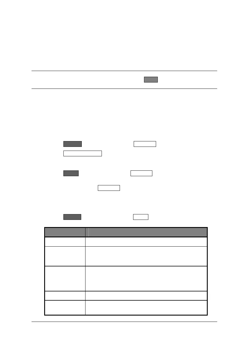
2. Set up triggering
Press the Channel hard key followed by the Trigger soft key. Use the soft keys
within the trigger menu to make the settings detailed below.
Item Required setting
Trigger Source: Internal A
Set Cap Time Enter a value suitable to display the full pulse with both
rising and falling edges. The capture time would
typically be about 20% longer that the packet length.
Set Trig Delay: Enter a value as required to delay the capture time with
respect to the trigger event. A negative value must be
entered to display pre-trigger information as shown in
the figure at the end of this chapter.
Type: Rising
Set Trig Level: Enter a value below the power level to be measured. A
typical value would be in the region of –5 dBm.

 Loading...


