Home
Anritsu
Measuring Instruments
ML2480B Series
Anritsu ML2480B Series User Manual
4
of 1
of 1 rating
297 pages
Give review
Manual
Specs
To Next Page
To Next Page
To Previous Page
To Previous Page
Loading...
ML248xA / ML249xA
Common Procedures
5-92 13000-00162
September 2005
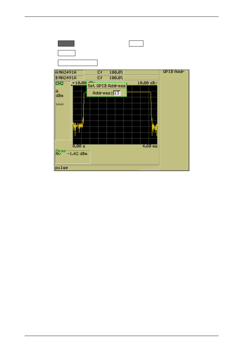
Setting the GPIB Address for the Instrument
1. Press
the
Syst
em
hard key followed by the
Config
soft key.
2.
Press the
Remot
e
soft key.
3.
Press the
Set GPIB Address
soft ke
y display the [Set GPIB Address] dialog.
4.
Enter the GPIB address at the numeric keypad in the usual manner
.
149
151
Table of Contents
default chapter
3
Limitation of Warranty
3
Notice about Documentation
3
Trademark Acknowledgements
3
Safety Symbols
4
For Safety
5
Declaration of Conformity (Ml248Xa)
6
Declaration of Conformity (Ml249Xa)
7
Table of Contents
8
Chapter 1. About this Manual
15
Purpose and Scope of this Manual
16
Your Comments on this Manual
16
Software Versions
16
Notification of Software Release
16
Using this Manual
17
Associated Documentation and Resources
19
Notation Conventions Used in this Manual
20
Chapter 2. Product Overview
21
About the Ml248Xa / Ml249Xa Peak Power Meter
22
Model Types
22
Features
23
Options and Accessories
24
Associated Sensors
25
Sensor Accessories
26
Associated Products
26
Chapter 3. Assembly and Connections
27
Initial Inspection
28
Shipped Items
28
Storage and Repackaging
29
Preparation for Storage
29
Environmental Requirements
29
Preparation for Shipment
29
Rack Mounting
29
Single Unit Rack Mounting (Option 01)
30
Tools Required
30
Assembly Procedure
31
Side-By-Side Rack Mounting (Option 03)
34
Tools Required
35
Assembly Procedure
35
Power Requirements
38
Environmental Requirements
38
Rear Panel Connections
39
Chapter 4. Front Panel Layout and Operation
41
Power-On Procedure
42
The Front Panel
43
The Numeric Keypad
44
The Hard Keys
46
The Screen
47
Sensor Information
48
Channel Information
49
Status Bar
52
The Soft Keys
53
Dialog Boxes
55
The Connectors
56
Data Entry Procedure
57
Numeric Entry Example
57
Text Entry
58
Power-Off Procedure
58
Chapter 5. Common Procedures
59
How Do I
60
Channel
68
Understanding and Setting up the Channels
68
Sensor Inputs
68
Channels
68
Modes
68
Measurement Displays
69
Channel Configuration Overview
70
Selecting the Measurement Mode
71
Selecting the Measurement Type
72
Selecting the Measurement Display Style
74
Selecting the Sensor Input (ML2488A and ML2496A Only)
75
Setting the Units of Measurement
77
Selecting the Resolution
78
Entering the Settling Percentage
79
Selecting Dual Display Channel Mode
80
Setting up the Second Channel
80
Displaying both Channels Simultaneously
81
Understanding Triggering
82
Selecting the Triggering Mechanism
83
Selecting the Type of Triggering
84
Entering the Triggering Capture Time
85
Random Repetitive Sampling (RRS) (Ml249Xa Only)
86
Entering the Triggering Delay
87
Enabling Auto Triggering
88
Entering the Triggering Level
89
Setting the Trigger Bandwidth (Ml249Xa Only)
90
Selecting the Trigger Arming Method
91
Entering a Frame Arming Level and Duration
92
Setting the Sampling Rate
93
Selecting the Trigger Indicator (Ml249Xa Only)
94
Linking the Channel Trigger Settings
95
Gates and Fences
96
Setting up and Enabling Gates and Fences
97
Viewing Gating Patterns
99
Setting the Active Gate
100
Setting up Repeat Gates
101
Averaging
102
Setting up Averaging
102
Enabling Averaging in Pulsed/Modulated Mode
103
Enabling Averaging in CW Mode
104
Restarting Averaging in Pulsed/Modulated Mode
104
Markers
105
Setting Markers
105
Turning All Markers off
106
Setting and Viewing the Active Marker
107
Positioning the Active Marker
107
Positioning the Delta Marker
108
Setting the Delta Marker Calculation
109
Linking the Delta Marker to the Active Marker
109
Moving the Active Marker to the Maximum Point
110
Moving the Active Marker to the Minimum Point
110
Zooming in or out on the Active Marker
110
Measuring the Pulse Rise Time
111
Measuring the Pulse Fall Time
112
Measuring the Pulse Width
113
Measuring the off Time
114
Measuring the Pulse Repetition Interval
115
Setting the Search Target Levels
116
Setting the Duty Cycle in CW Mode
117
Limits
118
Creating and Viewing Simple Limits
118
Creating and Saving Complex Limits
119
Recalling User or Predefined Complex Limits
121
Editing Complex Limits
122
Repeating Limits
123
Holding the Limit Fail Indicator
124
Sounding an Alarm on Limit Failure
124
Adjusting and Resetting the Trace Measurement Scale
125
Setting the Profile Display Style
126
Setting the Profile Display Data Hold Method
127
Holding Measurement Data in the Currently Active Channel
128
Setting the Peaking Indicator
128
Post Processing
129
Statistical Post Processing
130
PAE Post Processing
132
Setting the Cursor Position
133
Zooming in or out on the Cursor Position
133
Sensor
134
Setting up the Sensor in Use
134
Setting the Calibration Factor Applied to the Sensor
135
Setting the Power Offset Applied to the Sensors
137
Editing Cal Factor Tables
138
Creating New Cal Factor Tables
139
Editing the Sensor Offset Tables
140
Creating New Sensor Offset Tables
141
Holding Sensors on the Current Range
142
Cal/Zero
143
Zeroing the Sensor
143
Zeroing and Calibrating the Sensor
143
Performing a Zero Dbm Calibration
144
Zeroing the Rear Panel BNC Connector
144
System
145
Saving Instrument Settings
145
Recalling Instrument Settings
146
Capturing the Screen Image
148
Changing the Brightness of the Display Backlight
149
Setting the GPIB Address for the Instrument
150
Enabling Buffering of the GPIB Output
151
Setting the RS232 Serial Port Baud Rate
151
Configuring the Rear Panel Outputs
152
Turning the Key Click on or off
155
Setting Increment and Decrement Steps
155
Viewing the Instrument Identity Dialog
156
Turning the Security Feature on or off
156
Diagnostics
157
Upgrading the System Software
157
Preset
158
Resetting the System
158
Using the Preset Configurations
159
Chapter 6. Remote Operation
161
Overview of GPIB
161
Chapter 7. CW Setup and Measurement
163
Setting up the Power Meter for CW Measurements
163
Chapter 8. GSM Setup and Measurement
165
Setting up the Power Meter for GSM Measurements
165
Chapter 9. CDMA Setup and Measurement
169
Setting up the Power Meter for CDMA Measurements
169
EDGE Setup and Measurement
171
Setting up the Power Meter for EDGE Measurements
171
WLAN Setup and Measurement
175
Setting up the Power Meter for WLAN Measurements
175
802.11B, A, and G
175
Radar Setup and Measurement
177
Setting up the Power Meter for Radar Measurements
177
OFDM Setup and Measurement
179
Setting up the Power Meter for Continuous OFDM Measurements
179
Chapter 14. Examples of Dual Display Channel Operation
181
Displaying a Measurement in Different Units
181
Displaying a Pulsed/Modulated Measurement in Different Modes
182
Chapter 15. Dual Sensor Operation (ML2488A / ML2496A Only)
183
Displaying Measurements from Two Sensors Simultaneously
183
Chapter 16. ML2419A Range Calibrator
185
Overview of the ML2419A Range Calibrator
186
Initial Inspection
186
Power Requirements
186
Environmental Requirements
187
Rack Mounting
187
Storage and Shipment
187
Front Panel Connections
187
Rear Panel Connectors
188
Performing Verification
189
Interpreting the Results
191
Pass/Fail Criteria
191
Range Change Error
192
Using the Diagnostics Menu
192
Using the Range Calibrator Config Menu
193
Chapter 17. Secure Mode
195
Types of Memory
196
Secure Mode
196
Clearing the Non-Volatile Static RAM
196
Anritsu Power Sensors EEPROM
197
EEPROM Contents
197
Appendix A. the Command Hierarchies
199
Channel - Set up (Pulsed/Modulated
200
Channel - Set up (CW
201
Channel - Trigger - Trigger Source
202
Channel - Trigger - Set Capture Time
203
Channel - Trigger - Set Trigger Delay
204
Channel - Trigger - Trigger Level
205
Channel - Trigger - Trigger Bandwidth (Ml249Xa Only
206
Channel - Trigger - more - Arming
207
Channel - Trigger - more - Set Sample Rate
208
Channel - Trigger - more - Trigger Indication
209
Channel - Gating - Set up (Pulsed/Modulated
210
Channel - Gating (Cont) (Pulsed/Modulated
211
Channel - Relative Meas (CW
212
Channel - Averaging - Set Avg Number (Pulsed/Modulated
213
Channel - Averaging - Set Avg Number (CW
214
Channel - Markers - Position Act Mkr (Profile
215
Channel - Markers - Assign Act Mkr (Profile
216
Channel - Markers - Delta Marker - Position Delta Mkr (Profile
217
Channel - Markers - Set up (Profile
218
Channel - Markers - Marker Functions - Advanced Functions (Profile
219
Channel - Duty Cycle (CW
220
Channel - more - Limit Checking - Set up (Pulsed/Modulated
221
Channel - more - Limit Checking - Edit Limit Spec - Select Spec
222
Channel - more - Limit Checking - Edit Limit Spec - Save Spec
223
Channel - more - Limit Checking - Edit Limit Spec - Edit Segments
224
Channel - more - Limit Checking - Edit Limit Spec - Edit Title
225
Channel - more -Scaling (Profile
226
Channel - more - Profile Display (Profile
227
Channel - more - Peaking Indicator (Pulsed/Modulated
228
Channel - more - Peaking Indicator (CW
229
Channel - more - Post Process - Set up
230
Channel - more - Post Process - Cursor
231
Sensor - Setup
232
Sensor - Cal Factor
233
Sensor - Edit Tables
235
Sensor - Edit Tables - Edit Identity
236
Sensor - Edit Tables - Edit Offset Table
237
Cal/Zero
238
System - Save / Recall
239
System - Recall Settings
240
System - Config - Display - Set Screen Title
241
System - Config - Display - Backlight
242
System - Config - Remote - Set RS232 Baud Rate
243
System - Config - Rear Panel Config
244
System - Config - Set Inc/Dec Steps
245
System - Service - Identity
246
System - Service - Diag
247
System - Service - Upgrade
248
Preset
249
Appendix B. Specification
251
Appendix C. Default Values and Presets
262
Appendix D. ML2400A Reference Table
279
Appendix E. Terminology Glossary
281
Appendix F. Technical Support
283
Appendix G. Uncertainty Information
285
Uncertainty Examples
285
Appendix H. Frequently Asked Questions
287
Appendix I. Connector Care and Handling
289
Other manuals for Anritsu ML2480B Series
Maintenance Manual
100 pages
4
Based on 1 rating
Ask a question
Give review
Questions and Answers:
Need help?
Do you have a question about the Anritsu ML2480B Series and is the answer not in the manual?
Ask a question
Anritsu ML2480B Series Specifications
General
Brand
Anritsu
Model
ML2480B Series
Category
Measuring Instruments
Language
English
Related product manuals
Anritsu ML248 A Series
297 pages
Anritsu ML2437A
314 pages
Anritsu ML2438A
314 pages
Anritsu MS2024B
256 pages
Anritsu MT8212E
640 pages
Anritsu MS2722C
112 pages
Anritsu MT8820A
296 pages
Anritsu MS9710C
269 pages
Anritsu MT1810A
272 pages
Anritsu MX269018A
1452 pages
Anritsu Sire Master S331D
102 pages
Anritsu VNA Master MS2026C
160 pages

 Loading...


