13000-00162 12-1
September 2005
Chapter 12. Radar Setup and Measurement
Setting Up the Power Meter for Radar Measurements
Follow the procedure below to set up the ML248xA / ML249xA to perform Radar
measurement on single pulses.
Note: There are two Radar options in the [Preset] dialog which can also be used to
automatically configure the unit for single pulse radar measurement. Press the Preset
hard key and then use the arrow keys to select either option 15 Radar 200ns or option 16
Radar 5µs. These will set the display time up to either 200ns (RRS mode) or 5µs for
capturing a radar pulse. Trigger is set to Internal A.
1. Perform calibration
Connect the sensor in use to the input on the front panel.
Connect the RF port of the sensor to the “Calibrator” input on the front panel.
Press the Cal/Zero hard key followed by the Zero & Cal soft key.
Press the Zero & Cal Sensor soft key for the input in use. The sensor is now
calibrated and a message displays on the screen when calibration is complete.
Remove the sensor from the “Calibrator” input when complete.
Press the Sensor hard key followed by the Cal Factor soft key to display the [Cal
Factor] dialog.
Use the soft keys to select Frequency at the “Source” item, and then enter the
required frequency after selecting the “Frequency” item. Correction data is read from
the EEPROM in the sensor and applied automatically to the measurement based on
the input frequency.
2. Select the type of measurement to be made on the data.
Press the Channel hard key followed by the Set Up soft key. Use the down arrow on
the keypad to select the “Measurement” item and then use the soft keys to select the
measurements to be made. Refer to the explanation in chapter 5 of this manual in
the section titled “Selecting the Measurement Type”.
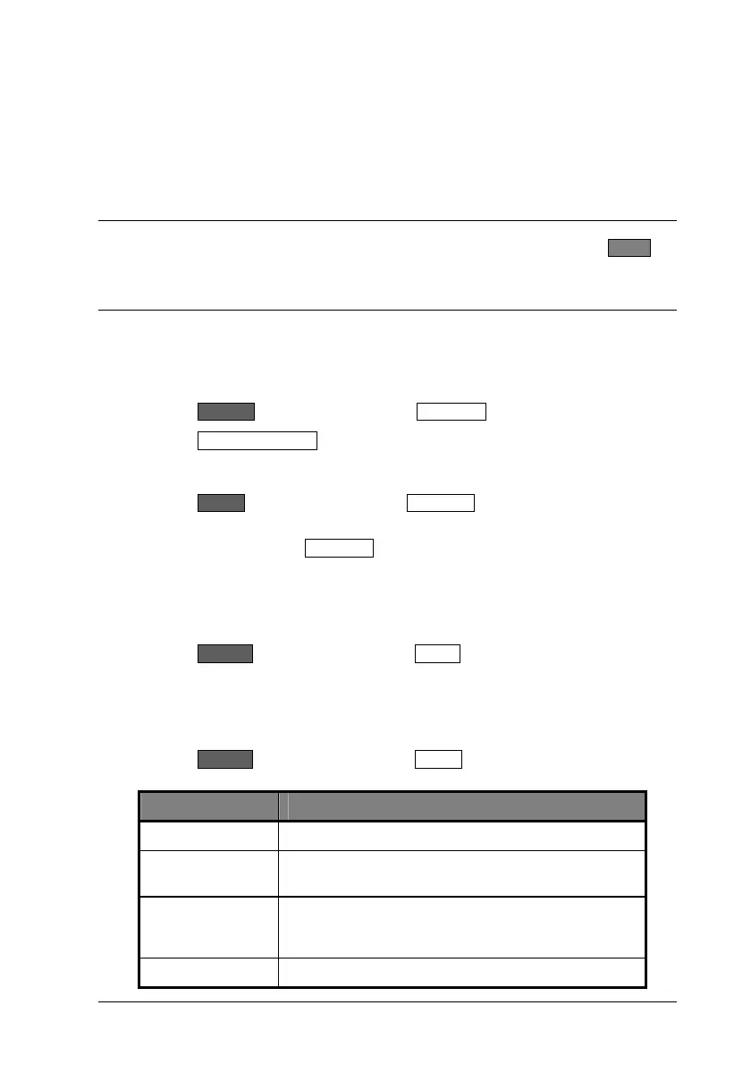
3. Set up triggering
Press the Channel hard key followed by the Trigger soft key. Use the soft keys
within the trigger menu to make the settings detailed below.
Item Required setting
Source: Internal A (can also use external)
Capture time: The capture time should be sufficient to accommodate
the pulse being measured, e.g., 200ns or 5µs
Delay: A negative delay value represents the time before the
trigger allowing the user to display the pre-trigger
information.
Type: Rising

 Loading...


