13000-00162 7-1
September 2005
Chapter 7. CW Setup and Measurement
Setting Up the Power Meter for CW Measurements
Follow the procedure below to set up the ML248xA / ML249xA to perform continuous
wave measurement.
Note: Either of the channels can be set up for CW measurement in the manner described
below, but it should be noted that channel 2 is already preset for CW measurement.
1. Perform calibration
Connect the sensor in use to the input on the front panel.
Connect the RF port of the sensor to the “Calibrator” input on the front panel.
Press the Cal/Zero hard key followed by the Zero & Cal soft key.
Press the Zero & Cal Sensor soft key for the input in use. The sensor is now
calibrated and a message displays on the screen when calibration is complete.
Remove the sensor from the “Calibrator” input when complete.
Press the Sensor hard key followed by the Cal Factor soft key to display the [Cal
Factor] dialog.
Use the soft keys to select Frequency at the “Source” item, and then enter the
required frequency at the keypad after selecting the “Frequency” item. Correction
data is read from the EEPROM in the sensor and applied automatically to the
measurement based on the input frequency.
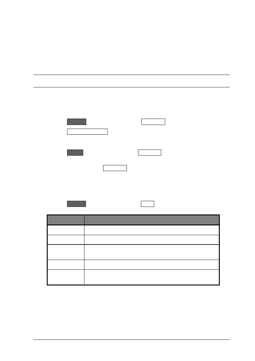
2. Set up the channel
Press the Channel hard key followed by the Setup soft key to display the [Channel
Set Up] dialog. The settings required in this dialog are detailed below.
Item Required setting
Mode: CW
Input Config: Set to the input in use.
Units: Select the required units. The default setting is dBm and
this is suitable for CW measurement.
Resolution: The default setting of n.nn is suitable.
Settling%: Enter a settling percentage as required. A 1% settling time
value relates to approximately 0.04 dB.

 Loading...


