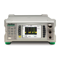
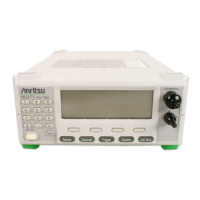
ML248xA / ML249xA Front Panel Layout and Operation
4-8 13000-00162
September 2005
Sensor Information
Sensor related information displays at the top of the screen (section A in the figure on the
previous page). On the ML2487A / ML2495A there is one line of sensor information, and
on the ML2488A / ML2496A, a second line is added beneath for sensor input B.
AB C D E F
A Sensor input letter
Displays the letter (either A or B) of the associated sensor input.
B Sensor model
Displays the model number of the sensor connected to the input.
C Measurement option
Information is displayed in this section if a Universal sensor with option
1 is connected to the input. If the user has selected the Fast CW
measurement option, ‘F-CW’ displays, otherwise ‘T-RMS’ displays for
the True RMS measurement option.
D Cal factor information
Displays the source and value of the calibration factor being applied to
the sensor. The following abbreviations are used to indicated the
source of the cal. Factor:
‘Cf’ Frequency - the calibration factor is derived from the cal factor
table using the input signal frequency.
‘Cm’ Manual - the user has set the calibration factor value.
‘Cv’ V/GHz - the calibration factor is derived from the cal factor
table using the frequency value that is proportional to the
voltage on the rear panel input.
E Offset information
The type of the offset and its value are displayed. The following
abbreviations are used to indicate the type of offset:
‘Of’ Fixed - the user has set the offset value.
‘Ot’ Table - the offset value is derived from the selected offset
table.
F Held range information
Information is displayed if the current sensor input is being held to a
single operating range.
 Loading...
