ML248xA / ML249xA Common Procedures
5-60 13000-00162
September 2005
Limits
Upper and lower limits can be used during measurement to check that the results of
measurement fall within an acceptable range. Limits can be set up by using one of those
already defined within the instruments firmware, or by creating either a simple or complex
limit specification.
Creating and Viewing Simple Limits
A simple limit is one with only one segment and is thus shown on the profile as a straight
line. The user can choose to set only an upper limit, only a lower limit, or both an upper
and a lower limit. Simple limits can be used in both CW and Pulsed / Modulated modes.
1. Press the Channel hard key followed by the More soft key.
2. Press the Limit Checking soft key to display the [Lim Check] group of commands.
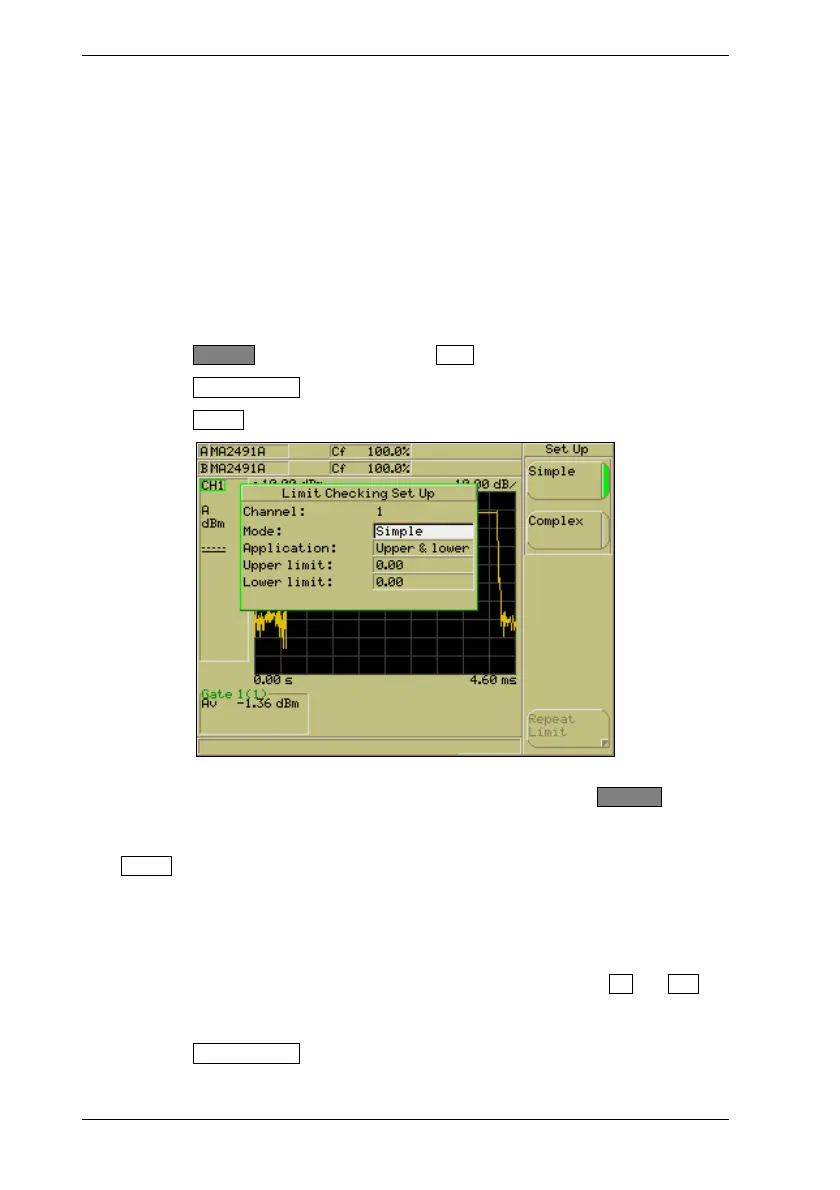
3. Press the Set Up soft key to display the [Limit Checking Set Up] dialog.
4. Make sure that the “Channel” item in the dialog is displaying the channel for which
the limit settings are required. If the channel is incorrect, press the Ch1/Ch2 hard
key to change the active channel.
5. The “Mode” item is selected automatically when the dialog is opened. Select the
Simple soft key.
6. Press the down arrow on the numeric keypad to select the “Application” item in the
dialog and then use the soft keys to select either upper and lower limits, upper only,
or lower only.
7. Press the down arrow on the numeric keypad to select the upper and / or lower limit
setting item(s) in the dialog and enter the required value(s) using the Inc and Dec
soft keys, or from the keypad in the normal manner. Press [Exit] when all settings
are complete.
8. Press the Limit Checking soft key in the [Lim Check] menu to enable and display the
limits on the screen. When limit checking is enabled, the green LED on the soft key
is lit and the word “Limit” displays at the left side of the screen.

 Loading...


