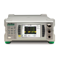
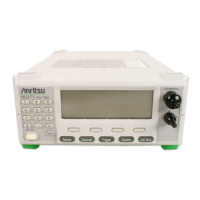
Front Panel Layout and Operation ML248xA / ML249xA
13000-00162 4-7
September 2005
The Screen
The screen on the ML248xA / ML249xA can be sub-divided into several sections, each of
which is illustrated and explained below.
B
C
D
E
F
G
HI
A Sensor related information.
B Profile display icon.
C Channel related information.
D Area for profile and readout displays.
E Sample rate display.
F Gating and statistics related information.
G Status bar for error message and status reports.
H Marker and cursor related information.
I Soft key commands.
Note: The figure above represents the screen when the measurement display setting is
set to “Profile”. When viewed in “Readout” mode, sections B, E, F, and H are not
displayed. Refer to “Selecting the Measurement Display Style” in chapter 5 of this manual.
 Loading...
