Chapter 3 — Performance Verification 3-9 50 MHz Calibrator VSWR Verification (All Models)
ML248xx, ML249xA MM PN: 13000-00164 Rev. K 3-15
10. Repeat step 4 through 9 to measure and record the measurements for the 200, 300, 400 Ohm settings.
11. Record the 4 resistance measurements below:
R
100
= ______________ (A value near 100 ohms)
R
200
= ______________ (A value near 200 ohms)
R
300
= ______________ (A value near 300 ohms)
R
400
= ______________ (A value near 400 ohms)
12. Power off the N432A.
13. Attach the 8478B power sensor to the sensor cable.
14. Do not connect the power sensor to any source.
15. Power on the N432A.
16. Allow the N432A to zero the power sensor.
17. After zeroing is complete, attach the power sensor to the S820E or equivalent VNA.
18. Measure the VSWR at 50 MHz for each of the 4 resistance settings and record below:
VSWR
100
= ______________
VSWR
200
= ______________
VSWR
300
= ______________
VSWR
400
= ______________
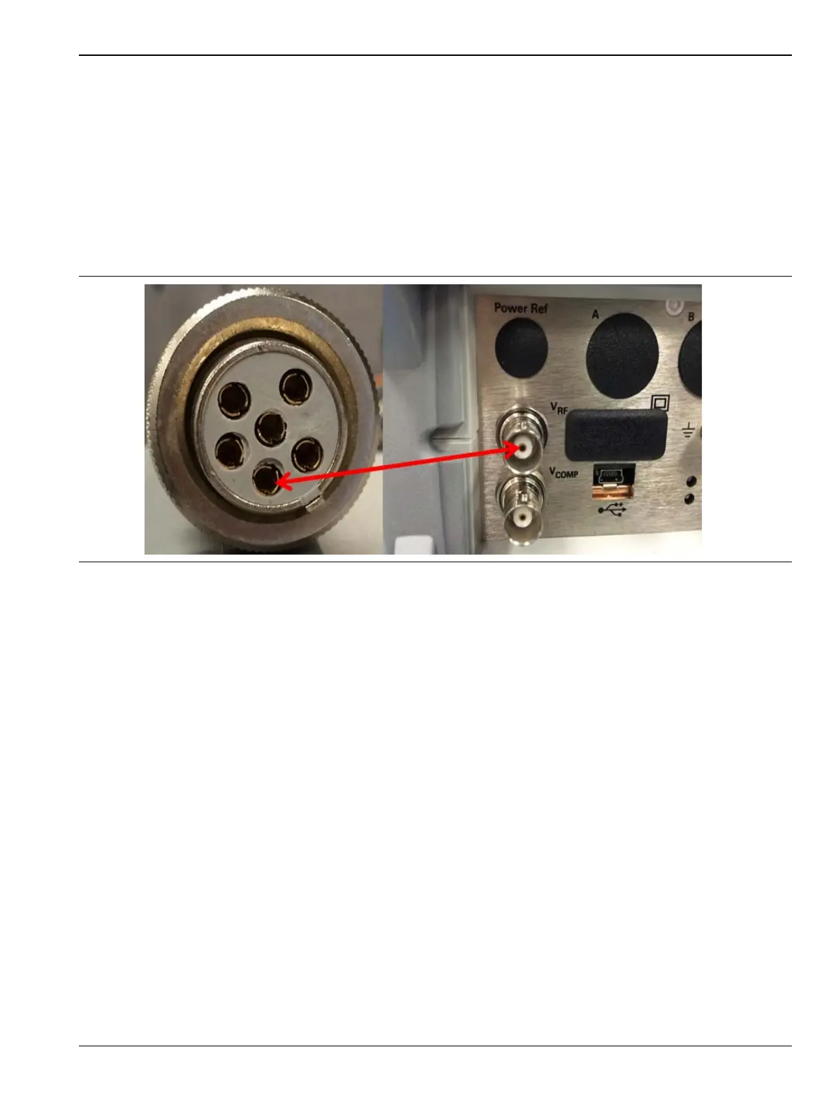
Figure 3-6. 100, 200, 300 and 400 Ohm Bridge Resistance Measurement
 Loading...


