3. Startup
15
3 Getting Started
This chapter describes names and functions of the front panel, rear panel, and screen
display and provides the basic procedures for operating the AT682/683.
Front Panel Summary
Real Panel Summary
Power-up
Begin Measuring
3.1 Front Panel
3.1.1 Front Panel Summary
Charge
Rate
Range
Remote
Shift
View
I/R
Brightness
0
.
+/-
1
2 3
4
5
6
7
8 9
Trig
Esc Enter
p
n
m
k
M
G
Trigger
AT682 Megaohmmeter
Disch
Refer
Voltage
Timer
1
2
3
5
6
7
Admin
!Applent
Beep
Beeper
Clear
UNKNOWN
(+)
(-)
HV
Rx
!
4
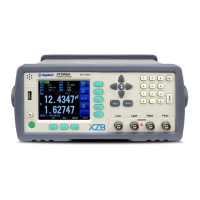
Figure 3-1 Front Panel
1. Power Switch
To apply power to the instrument, Push Down: ON, Push Up: OFF
2. Display
VFD Screen,
Displays measurement results, instrument status and user’s interface
menus.
Full VFD Content Includes in section “3.1.3 VFD”.
3. Knob
To Choose Menu Item and Input Number
4. Terminals
+ BNC (Red) (Sense)
- High Negative Voltage Output (Black) (Drive)
GND Ground (Red) (Ground Terminal for jumper of (+) Input Terminal or
Guard Input to Chassis GND)