3. Startup
21
3.4 Measurement configuration
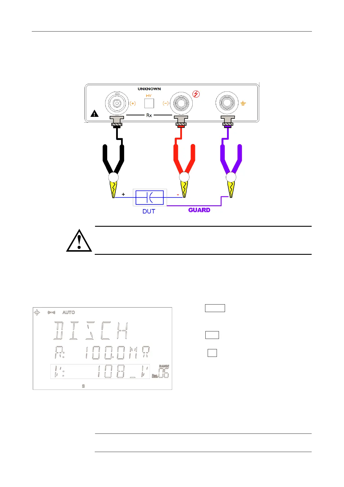
3.4.1 Connection to Device under Test (DUT)
Figure 3-6 Connection to DUT
WARNING:
When the HV LED is lit, No touching the device under testing, the lead wires or the
output terminals.
3.4.2 Voltage
Voltage Input box accepts entry of a test voltage between 1.0 and 1000 VDC. <100V in
0.1V intervals, 100V in 1V intervals.
1. Press Voltage key, a cursor flashed at 3
rd
line on
the VFD.
2. Press Numeric Key Enter value.
3. Press Enter to finish input, the Value will save in
Flashrom and back to Discharge State.
Press Esc key to cancel input and back to
Discharge State.
3.4.3 Range
Full Resistance Range in the Appendix A.