5. Handler Interface
29
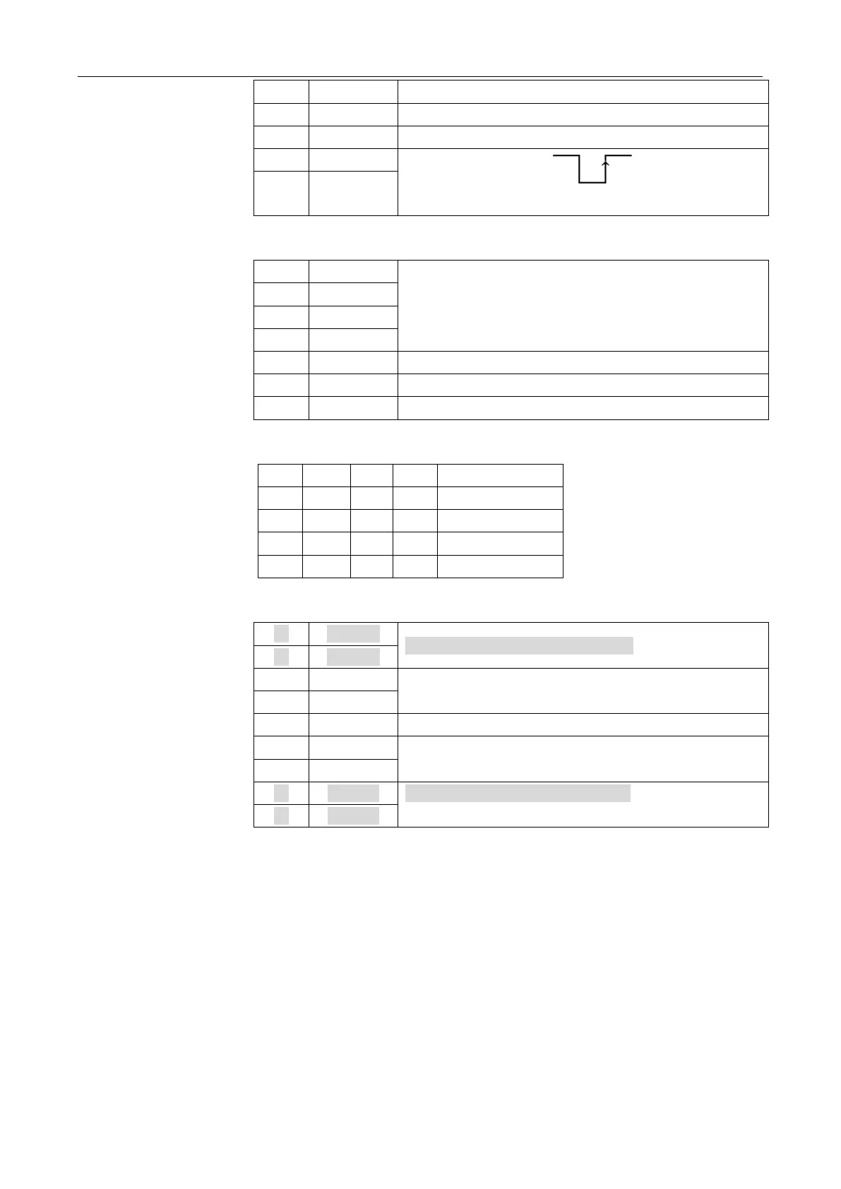
External Trigger Signal (Rising edge)
17-18 SHORT = TRIG5V
Table 5-3 Output Signals
Measurement completion signal. (Low)
Table 5-4 Typical Voltage Control Signal
Table 5-5 Power Signal
Internal GND: Not Recommend to use
External VCC2: Pull-up Resistance(5k) Power Supply
External VCC1: Main Power Supply
Internal 3.3V: Not Recommend to use
5.2 Electrical Characteristics
Input Signal:
Each input signal is connected to the LED (cathode side) of the photo-coupler. The LED
(anode side) is connected to the pull-up power supply voltage.
Output Signal:
Each output signal is outputted via an open collector by using a photo-coupler. The voltage
of each output is obtained by connecting pull-up resistors, inside or outside of the
AT682/683.