AT682/683 User’s Manual
30
NOTE:
If the external power supply greater than 8VDC, use external pull-up resistance please.
The Pin 32 leaves float.
The output signal current can not drive relay.
Power supply
The power supply for the judgment output signal pull-up and that for the operation output
signal pull-up and input signal drive can be set separately. You can select +3.3V of the
internal power supply or from +3.3V to +24V external power supply.
1
2
4
3
R
4 99
E XT .D CV
INPU T
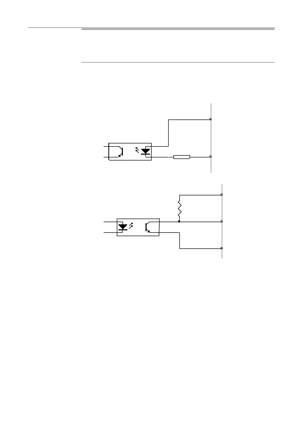
Figure 5-2 Typical Circuit Diagram of Handler Interface Input signals.
1
2
4
3
R
4 .99 k
E XT .D CV
O UT PU T
G ND
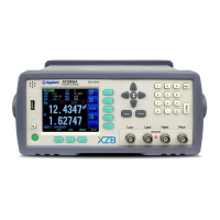
Figure 5-3 Typical Circuit Diagram of Handler Interface Output signals.