EasyManua.ls Logo

APT WorldCast Equinox - 4.5.7. Opto-coupler;Isolator Inputs

APT WorldCast Equinox
170 pages
Print Icon
To Next Page IconTo Next Page
To Previous Page IconTo Previous Page
Loading...
WorldCast Equinox - Release 3.1 - user manual 07/2011
Page 32
Whiterock Business Park - 729 Springfield Road - Belfast BT12 7FP - Northern Ireland
Tel.: +44 28 9067 7200 | Fax: +44 28 9067 7201 | http://www.aptcodecs.com | contact@aptcodecs.com
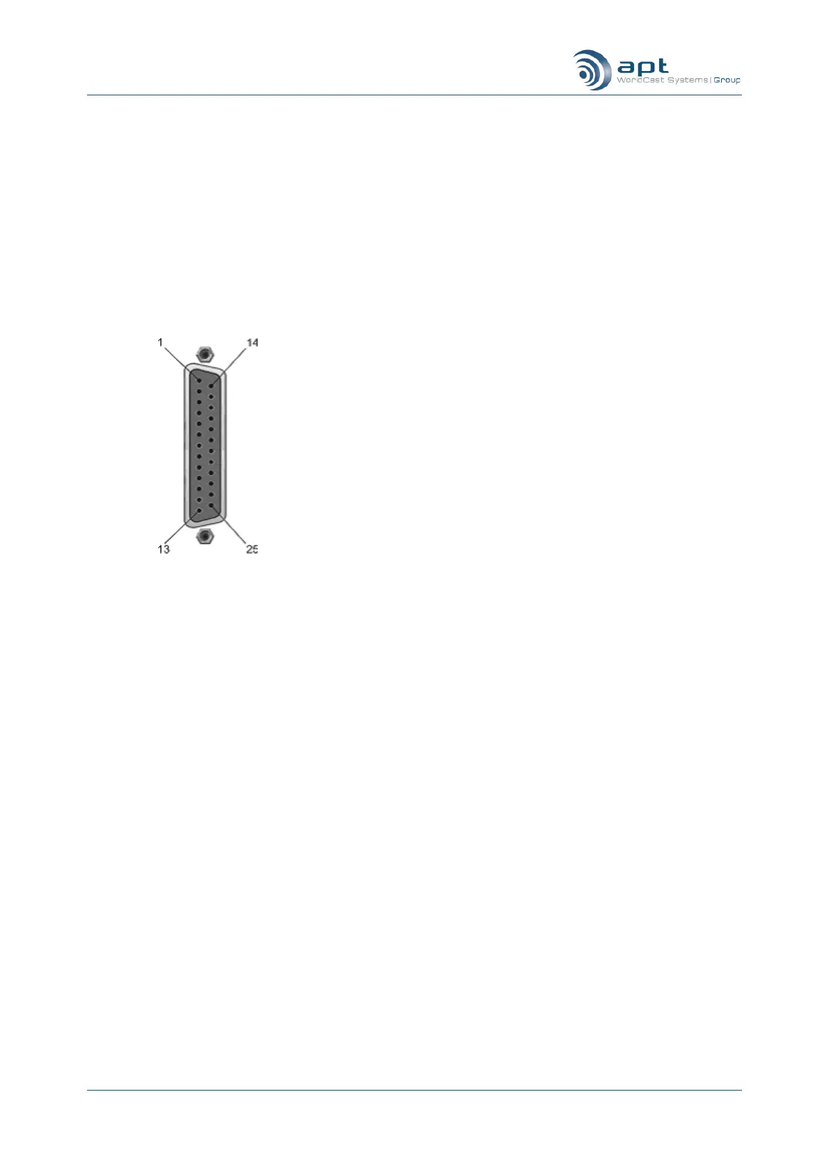
4.5.7. Opto-coupler/Isolator
25 pin female connector
contact view
Alarm Port
Selected by pins
Pin
Description
Function
1
+ve Alarm 1
Alarm 1 +ve I/P
2
Clean Alarm 1
Alarm 1 Contact I/P
3
+ve Alarm 2
Alarm 2 +ve I/P
4
Clean Alarm 2
Alarm 2 Contact I/P
5
+ve Alarm 3
Alarm 3 +ve I/P
6
Clean Alarm 3
Alarm 3 Contact I/P
7
+ve Alarm 4
Alarm 4 +ve I/P
8
Clean Alarm 4
Alarm 4 Contact I/P
9
+ve Alarm 5
Alarm 5 +ve I/P
10
Clean Alarm 5
Alarm 5 Contact I/P
11
+ve Alarm 6
Alarm 6 +ve I/P
12
Clean Alarm 6
Alarm 6 Contact I/P
13
+ve Alarm 7
Alarm 7 +ve I/P
14
Clean Alarm 7
Alarm 7 Contact I/P
15
+ve Alarm 8
Alarm 8 +ve I/P
16
Clean Alarm 8
Alarm 8 Contact I/P
17
-ve Alarm 1
Alarm 1 -ve I/P
18
-ve Alarm 2
Alarm 2 -ve I/P
19
-ve Alarm 3
Alarm 3 -ve I/P
20
-ve Alarm 4
Alarm 4 -ve I/P
21
-ve Alarm 5
Alarm 5 -ve I/P
22
-ve Alarm 6
Alarm 6 -ve I/P
23
-ve Alarm 7
Alarm 7 -ve I/P
24
-ve Alarm 8
Alarm 8 -ve I/P
25
GND
Ground
The opto-coupler, a 25 way „D‟ type female connector, will accept
a mix of up to a maximum of eight DC inputs. Either the voltage is
applied between +ve and ve (up to +30V) or Clean Alarm is
connected to GND. These signals are then converted to data and
embedded in the main data stream.
Connecting Clean Alarm inputs to Gnd may cause ground loops
and affect audio quality. If this happens use the opto-coupled in-
puts (+ve and ve) instead.
When the Remote Status feature is enabled, the contacts of
alarm relays 1 to 6 on both the local and remote codecs are dis-
connected from their normal operation and their circuits are con-
trolled by other unit‟s opto-coupled inputs. The alarm circuitry can
now be now used to transport any user defined control or moni-
toring signal. The Summary alarm is not affected and remains ac-
tive as before.

Table of Contents