17
5.3 OPERATION WITH A SPEED SENSOR
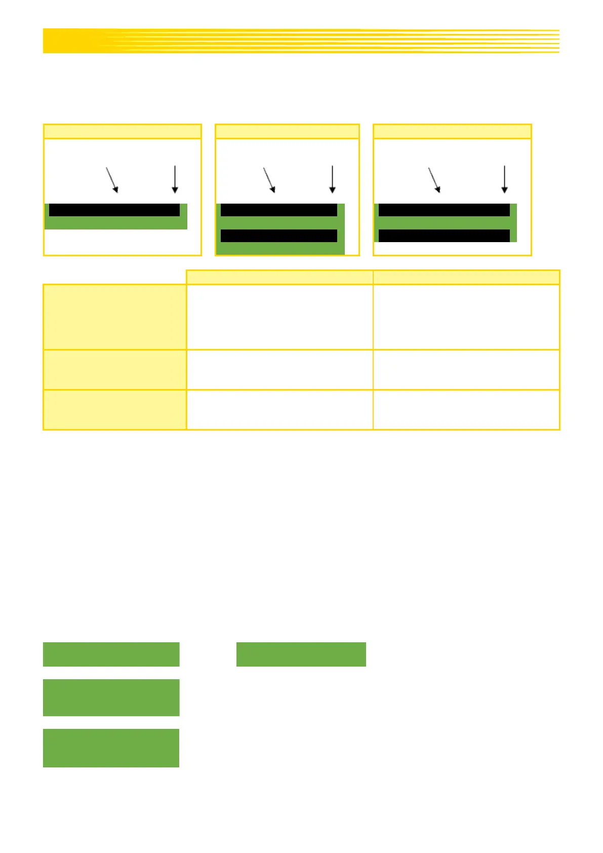
When working with a speed sensor, the display looks as follows:
Set speed of the seeding shaft (in
%). Setting using the plus/minus
buttons on the main screen of the
control box or by performing a
calibration test.
Actual speed of the seeding shaft (in
%). Is calculated and displayed by
the control box depending on the
forward speed.
Set motor revolutions (in %). Setting
using the plus/minus buttons on the
main screen of the control box.
Actual motor revolutions (in %).
Is set in the "Calibration test" menu
point.
Actual forward speed in km/h. Is
measured by the sensor and shown
on the control box.
5.3.1 PRE-SEEDING
When the OK button is pressed and held for 1 second, the seeding shaft starts rotating at the speed
determined by the calibration test as long as the OK button remains pressed. This allows you to avoid
gaps in the seeded area (at the beginning of the field or when standing still on the field). As soon as the
button is released again, the control box works with the signals from the respective speed sensor again.
When working with a linkage sensor, the soil tillage implement must be "in working position".
5.3.2 CALIBRATING THE FORWARD SPEED (TACHOMETER)
The calibration should be performed because the control box uses this value as a basis for all calculations
(speed display, metering, area calculation).
There are 3 options for the calibration:
5.3.2.1 TEST DISTANCE 100 M
Drive a distance of exactly 100 m. While driving, the control box counts the
pulses for the travelled distance on the display.
Stop with the OK button after 100 m.

 Loading...