33
Number of magnets:
Installation instructions:
For the optimal alignment of 6 magnets, it is best to use a compass (e.g. a string) to form an even
hexagon.
The magnet does not need to be bolted on. It is attached to steel rims through its high magnetic
force.
Route the cable through a well-protected area to avoid any damage (e.g. from the wheel).
Do not install the wheel sensor on the cardan shaft because its rotational speed is too high and
this may cause errors!
There may not be more than 15 pulses/m.
Scope of delivery: 1 sensor and 2 fastening nuts, 8 Neodym magnets (very strong), cable ties,
1 fastening plate
9.5 ACCESSORIES KIT FOR LINKAGE SENSOR CHASSIS MX
Through this sensor, the seeding shaft of the implement can start and
stop rotating automatically when lifting and lowering the implement.
Order number: 00410-2-173
Connection: 12-pin plug on the control box
Settings: see chapters 8.8 and 8.9
Cable length: 5 m
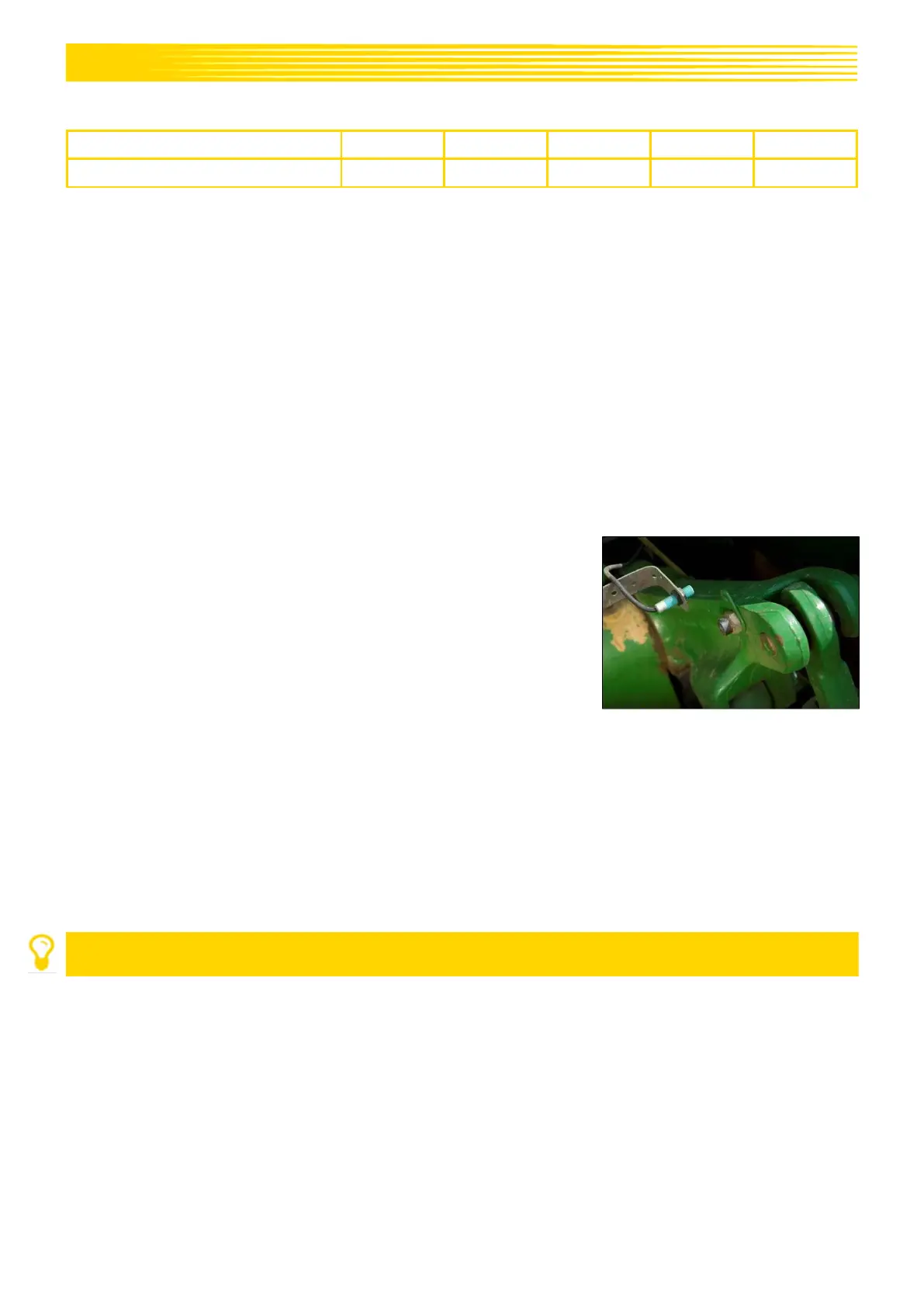
Installation position: Since most soil tillage implements are lifted and lowered during their operation,
installing the sensor on the tractor's lifting arm is the best method (see Figure 11).
However, the sensor can also be attached at other positions that have a
mechanical movement of more than 50 mm. The distance between the sensor and
the magnet should be approx. 5 mm. For semi-mounted soil tillage implements,
the sensor can be installed on the chassis, because the linkage is not used in this
case. The programming (position in which work is performed) can be adapted for
this purpose.
NOTE!
The sensor must not be bolted on too strongly (tension)!
Scope of delivery: 1 sensor, 2 magnets incl. bolts, cable ties,
1 fastening plate, 2 PVC nuts for the sensor