6
After use of the implement and for road transport, the control box must be disconnected again (for various
safety-related reasons).
CAUTION!
If these instructions are not observed, damage may be caused to the control box!
If your tractor does not have a standard socket, it can be retrofitted with a cable set (see chapter 9
Accessories).
CAUTION!
If your battery is charged by a charger that is in "Start" operating mode, there can be voltage
peaks! These can cause damage to the electrical system of the control box if it is also connected
when the battery is being charged!
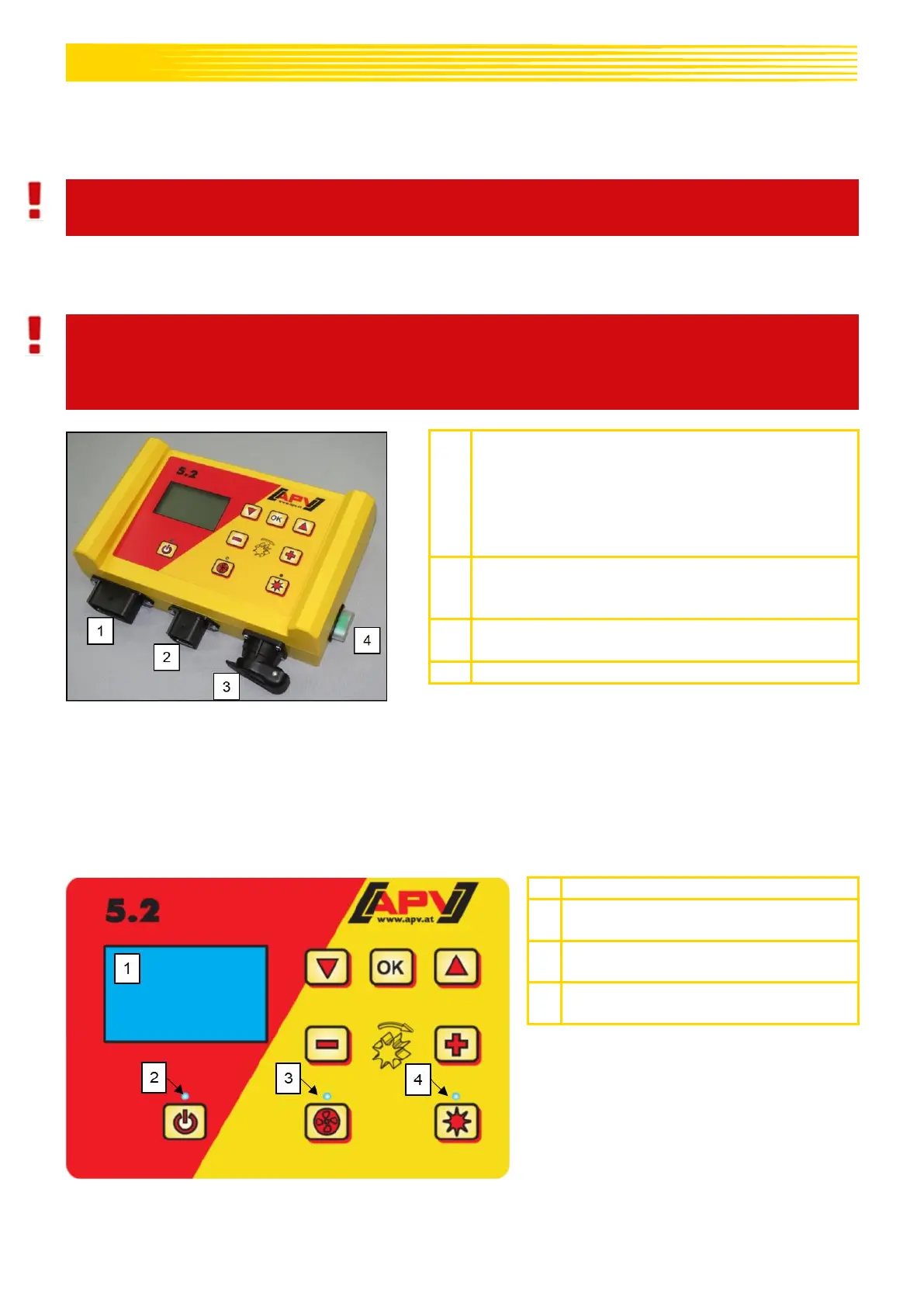
12-pin plug
Ground wheel
Amphenol (for standard socket)
Linkage sensor
Wheel sensor
Radar sensor
6-pin plug
Connection to the seed drill (implement
cable)
3-pin plug
Connection to the battery (power cable)
The different types of sensors are explained in more detail in chapters 5.3 and 5.4. They are available as
accessories upon customer request (see chapter 9 Accessories).
4.3 CONTROL BOX
Lights up when the controller is
switched on
Lights up when the fan or the
spreading plate is switched on.
Lights up when the seeding shaft is
rotating