Arkel ArLine User Manual V1.24
In the “Dimensions” section of this manual, the dimensions and templates required for the installation of this unit are given.
The mechanical installation of the external speaker and microphone will have an impact on the sound quality. The number of the
holes in front of the loudspeaker must be sufficient for the sound to pass. The microphone hole in the operating panel must be
aligned with the hole in front of the microphone to achieve maximum sound quality.
Alarm button, yellow and green pictograms (LEDs) are not included in the product, they are connected externally to the unit.
The operating panel supplier must have made the necessary preparation for the alarm button and pictograms.
Microphone, speaker and related connections are not included. The operating panel supplier must supply these parts. The
properties of these parts are as follows.
The speaker connection is non-directional. The microphone connection is directional. See Figure 15 for the microphone and
speaker connections.
6.3. Installation of Arkel ArLine-S-TP
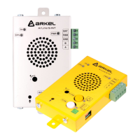
The Arkel ArLine-S-TP unit is designed to be placed in the well. On the unit, the alarm button, intercom button and yellow-
green pictograms and LEDs are internally present.
It can be installed on top of the car and under the car/in the pit (*) at a suitable location so that the alarm button can be pressed
from any refuge space within 30 cm horizontal distance.
*The speech unit can be installed under the car instead of the pit, provided that the requirements of the EN 81-20 standard are
met. The only way for personnel to be trapped in the pit is that the car closes the exit way of the personnel. In this method, there
will be no need to use additional wires in the pit for the speech unit.
Install the unit on an open and stable surface using suitable screws. If the front or sides of the unit are closed, this may cause
echo problems between the speaker and the microphone.
The location and dimensions of the mounting holes of this unit are shown in the “Dimensions” section of this manual.
6.4. Installation of Arkel ArLine-S-INT
The Arkel ArLine-S-TP unit is designed to be placed in the machine room or on the lift control panel. There is an intercom button
on the unit.
It should be located in the area where the emergency rescue operation is to be carried out (In the machine room or on the lift
control panel).
Install the unit on an open and stable surface, as appropriate. If the front or sides of the unit are closed, this may cause echo
problems between the speaker and the microphone.
The location and dimensions of the mounting holes of this unit are shown in the “Dimensions” section of this manual.
Type: Capacitive microphone
Voltage: Suitable for 5V operation