Arkel ArLine User Manual V1.24
COM
For programmable inputs + signal common.
It has the same potential as 100 and PWR terminals.
For programmable inputs - signal common.
It has the same potential as 1000 and GND terminals.
If CANbus serial communication is not used, these inputs should be used as required.
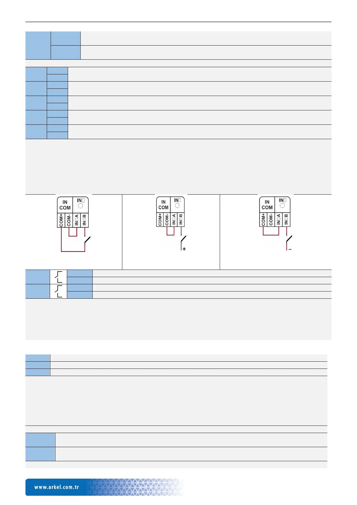
The inputs are insulated with a bidirectional opto-coupler, the connection is non-directional.
The signal common of the inputs is independent of each other.
Positive, negative or dry contact connection can be made.
It is triggered by voltage between 8-30V DC.
The status of the inputs is indicated by LEDs.
The functions that can be assigned to the programmable inputs are described in detail in the "Input functions" section.
The connection methods of the inputs are shown below.
Figure 7 Input connection with
internal supply
Figure 8 + (100) triggered input
connection
Figure 9 - (1000) triggered input
connection
Programmable relay 1 contact partner (COM)
Programmable relay 1 open contact output (NO)
Programmable relay 2 contact partner (COM)
Programmable relay 2 open contact output (NO)
Max. 1A @ 230V AC / 30V DC can be switched.
The relays must not be used to switch the lift safety circuit.
When the relays and inductive loads (Relay, contactor, etc.) are switched, the protection element must be used parallel to the
loads (Reverse diode in DC circuit, varistor or RC in AC circuit).
The status of the relays is indicated by LEDs. The functions that can be assigned to the programmable relay outputs are
described in detail in the section "Output functions".
7.2. Arkel ArLine-S-COP Connections
Supply+ from Arkel ArLine-M PWR terminal
Supply- from Arkel ArLine-M GND terminal
Communication line from Arkel ArLine-M CAR A-B terminals
BAT connector is not used, must be left blank.
The PWR-GND power supply via the Arkel ArLine-M has battery backup. 24V DC when there is power, 12V DC when
there is no electricity. For cable connection, the following must be observed in the travelling cable:
• Use 4 cables next to each other.
• The GND (1000) or PE line must be moved from the left and right of the cables if possible.
• These cables must be kept away from high-voltage cables and other cables that may cause electromagnetic
interference (Ex. door unlocking magnets).
See Figure 6 for connection to the Arkel ArLine-M unit.
+ signal common for alarm button input and pictogram outputs
It has the same potential as 100 and PWR terminals.
- signal common for alarm button input and pictogram outputs
It has the same potential as 1000 and GND terminals.
It is limited to a maximum of 200 mA.