Arkel ArLine User Manual V1.24
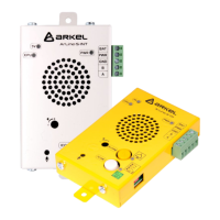
External alarm button input.
The input is insulated with an opto-coupler, the connection is non-directional.
Positive, negative or dry contact connection can be made.
It is triggered by voltage between 8-30V DC.
Alarm button connection methods are shown below.
Figure 10 Dry contact input
connection
Figure 11 + (100) triggered input
connection
Figure 12 - (1000) triggered input
connection
In Arcode and ARL-700 control systems, the following method can be used to connect the same contact to both the Arkel
ArLine-S-COP and the control system if the single contact alarm button is used.
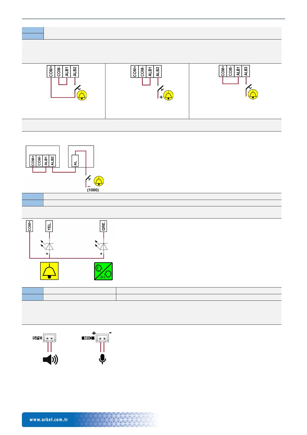
External green pictogram (Graphical symbol) LED output
External yellow pictogram (Graphical symbol) LED output
Max. 100mA, with transistor – (GND) output.
These pictograms and LEDs must be found in the operating panel and connections should be made as shown below.
External microphone connection
External speaker connection
The cables must be connected to their connectors as shown below.
The speaker connection is non-directional.
The microphone connection is directional. The connection must be made according to the ‘+’ and ‘-‘ directions indicated
for the MIC connector on the card.
CPC/CPC-T operating panel board
symbol
LED
Figure 14 External yellow-green LED connection
symbol
Figure 15 External microphone-speaker connection
Figure 13 Common connection of the alarm button in Arcode and
ARL-700 control systems