Arkel ArLine User Manual V1.24
5. Overview
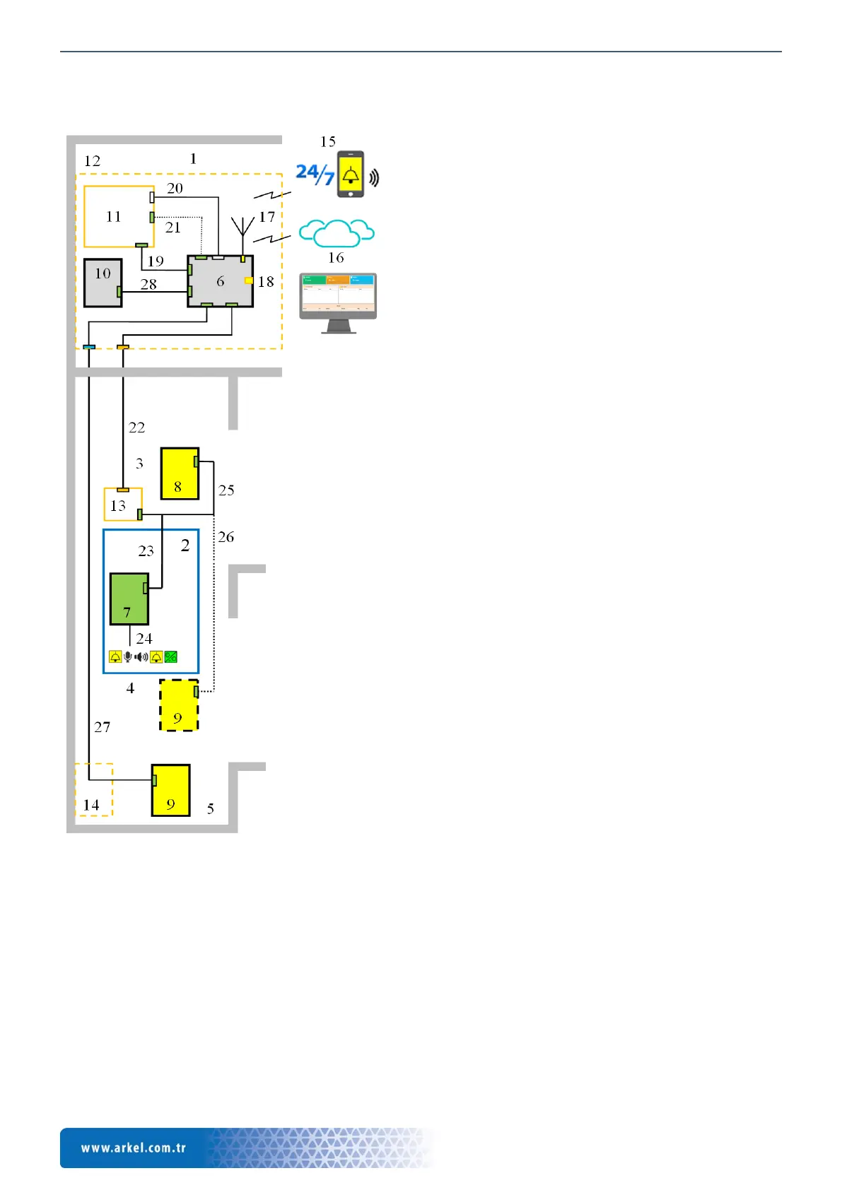
5.1. General Overview
2. Inside the car
3. Top of the car
4. Under the car
5. Pit
6. Arkel ArLine-M, main unit
7. Arkel ArLine-S-COP, car speech unit
8. Arkel ArLine-S-TP, top of car speech unit
9. Arkel ArLine-S-TP, pit (or under car) speech unit (* 1)
10. Arkel ArLine-S-INT, machine room/control panel intercom
11. Lift control unit
12. Lift control panel
13. Car top/inspection box
14. Pit box
15. Two-way communication with rescue service/staff
16. ARKEL Cloud remote lift management system
17. Antenna connection (GSM / GPRS)
18. SIM card
19. 24V DC supply (100, 1000)
20. CANbus connection with ARKEL control systems (* 2). Input-
output connections don’t need to be done in parallel.
21. Parallel input and output connections in systems other than
ARKEL.
22. Car speech unit connections.
With 4 wires via car travelling cable.
23. Arkel ArLine-S-COP connection (4 wires).
24. Arkel ArLine-S-COP external alarm button, microphone,
speaker, yellow and green pictogram connections.
25. Arkel ArLine-S-TP top of car connection (4 wires).
26. Arkel ArLine-S-TP under car connection (* 1) (4 wires).
27. Arkel ArLine-S-TP pit connection (* 1) (4 wires).
28. Arkel ArLine-S-INT, machine room/control panel intercom
connection (4 wires).
*1: The speech unit can be placed under the car instead of the pit,
provided that the requirements of the standard EN 81-20 are met.
Figure 1 An example overview of a system with machine room