2 of 3
P/N PM000120A • Rev. 1.0 • ISS 31MAY2017
To mount a spacer to a wall:
1. Place the spacer against a flat wall and orient it so that
“TOP” (printed on the inside of the spacer) is pointing up
and that the spacer is level. Use a leveling device to check,
if necessary.
2. Using the spacer as a template, mark two holes for the
screws using the outer fitting holes located in the corners
of the spacer.
3.
Remove the spacer and drill screw holes for the screws
that will be used, such as wood, concrete, or drywall
screws, or screws with anchors.
4. Remove the knock outs in the spacer for the cable wires.
5. Place the spacer over the holes, insert the screws, and then
tighten.
6. Pull the cables though the knock out holes.
Passive Bedside Module Connections and Jumper
The module connects to a passive room bus using an 8-pole
connector. It can also be daisy-chained with other peripheral
devices on same bus. The connector carries 5.5VDC power,
input, and output lines.
The module includes normally open solid state relays that
connect to a bed light’s lamp switching relays and allows the
handset to control the two bed lights.
The module also includes a jumper to activate an End-of-Line
resistor (EOL) when the module is last module on the passive
bus.
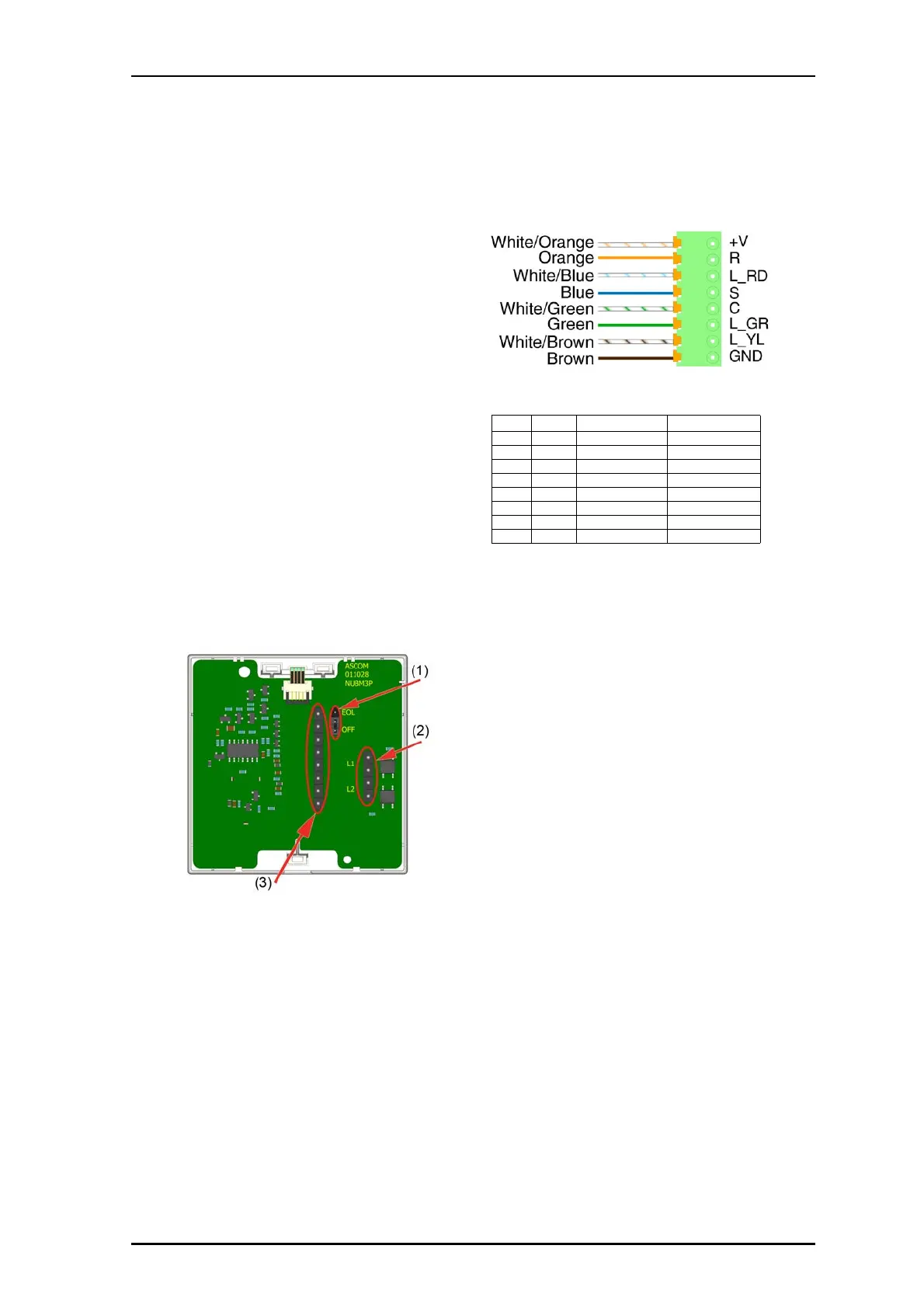
Legend
(1) Jumper for end-of-line (EOL)
(2) 4-pole connector connects to lamp switching relay
(3) 8-pole connector for controlling room lights
8-pole Block Passive Bus Connection Pinouts
To connect a passive bedside module:
1. Slide the cables with their connectors through a module
frame.
2. If this is the last device on the passive room bus, move
the EOL jumper to the first and second pins (labeled
EOL); otherwise, leave the jumper in its default posi
tion
(OFF). See the module connections figure, item 1.
Note: EOL must also be set in the system using the
Sys
tem Configuration Tool.
3. If using the module to operate the light switching relays,
attach the 4-pole connector cable for the light switching
re
lays to the 4-pin terminal See item 2. Ensure th
e
connector is seated properly on the pins. See "Light
Switching Relay Maximum Load and Surge Damping
Diode" below.
4.
Attach the 8-pole room bus connector cable to the
8-pin
terminal. See item 3. Ensure the connector is seated
properly on the pins.
Light Switching Relay Maximum Load and Surge Damping
Diode
The Bedside module includes two light switching circuits.
Each circuit is suitable for switching a bi-stable 24VDC
relay. The maximum switching current for each relay must
not exceed 0.2A at a maximum of 30VDC. A 4-pin
connector is needed to terminate the light switching relay
contacts.
External surge damping diodes are needed to protect the
switching relays on the NUBM3 module. An external power
source and external relay are needed for the light switching
Pin # Pin Description Color
1 +V Positive power Orange/White
2 R Reset Orange
3L_RDLED Red Blue/White
4S Set Blue
5 C C-line Green/White
6 L_GR LED Green Green
7 L_YL LED Yellow Brown/White
8 GND Ground Brown