P/N PM000223A • Rev. 1 • ISS 9 August 2017 13
Installation Manual
NU-Series Hardware
System Cabling
2. Check for a good connection by gently pulling on the wire after it is inserted. The wire
should stay fixed in the terminal.
3. Repeat steps 1 and 2 for the remaining wires.
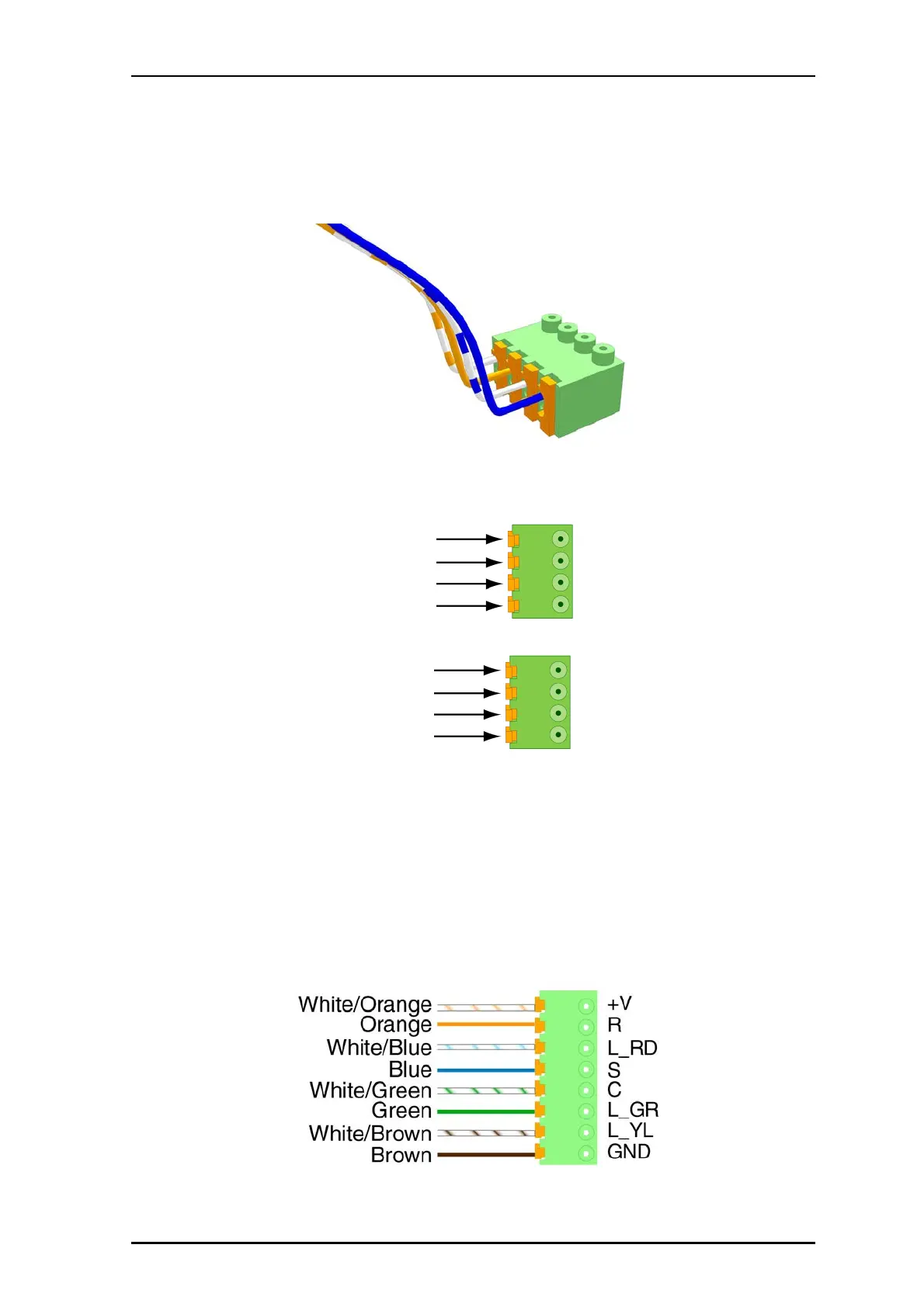
The following shows examples of 4-pole block connector wiring for a passive bus and for
the light relay.
Figure 9 4-pole block connector with passive pull cords
Figure 10 4-pole block connector for the light relay used with passive bedside module
2.4.3 Terminating Passive Room Bus Connectors
The passive bus consists of eight wires that carry +V, Ground, Reset, Set, C-line, and three
wires for lights with designated colors red, green, and yellow. Each bus can supply a
maximum of 100mA. The modules are connected to the NUPBC via 8-pole connectors.
These can be detachable spring case (part number NICT8-AA).
To terminate the 8-pole block connector for the passive bus, follow the instructions in
“Terminating Block Connectors” on page 12.
Figure 11 8-pole block connector (NICT8-AA) with passive bus connections