ascom
P/N PM000157A • Rev. 1.00 • ISS 4/13/17 1 of 2
© 2017 Ascom, Inc.
N U C P S - H K / N U E P S - H K C a r d i a c / E m e r g e n c y
Pull Switch Installation Sheet
Description
The NUCPS-HK and NUEPS-HK Pull Switch Modules are
devices that are suitable for general room applications.
The modules connect to an active room bus and are
typically mounted in a patient room.
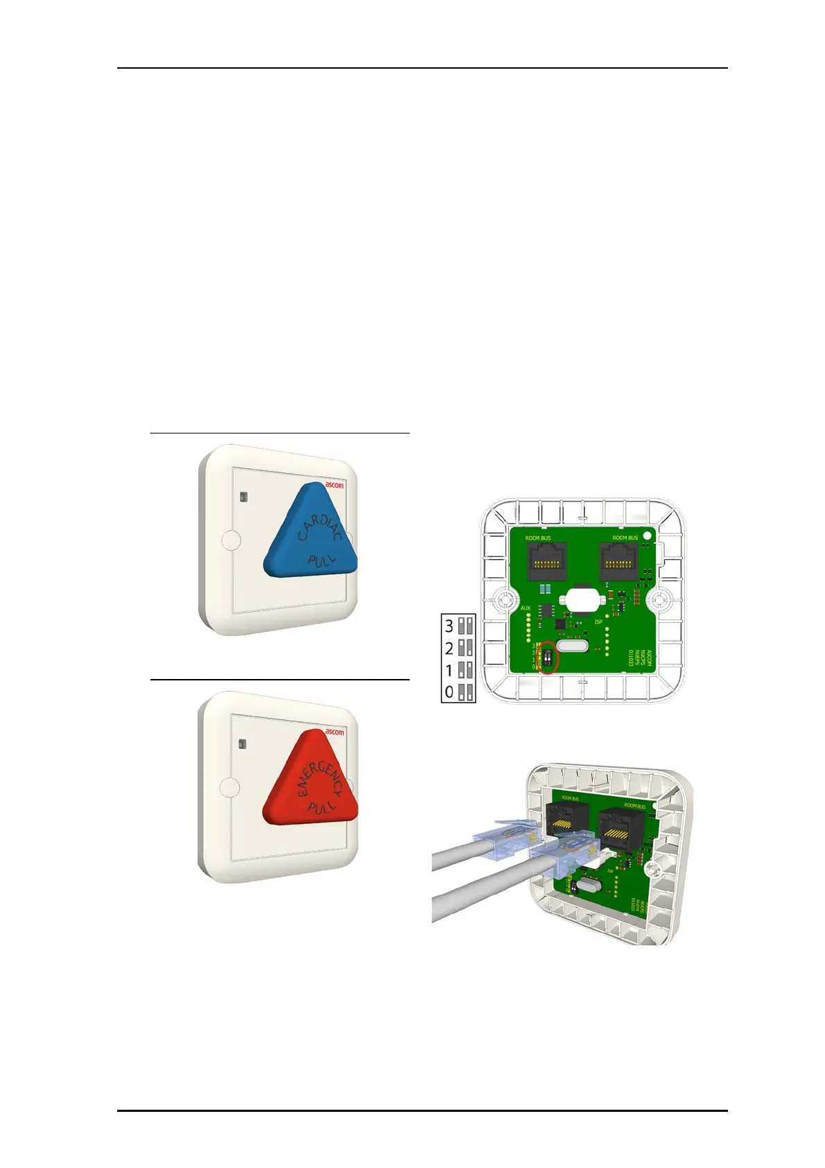
Pull Switch- NUCPS-HK Cardiac (Front)
Pull Switch-NUEPS-HK Emergency (Front)
Installation
Note: Before beginning the installation, ensure all the
necessary cables are available and are properly
terminated. RJ-45 connectors should be terminated in
accordance with the T568B or EIA 568B connection
standard.
The module can mount to a backbox or wall.
To make connections and to mount the module:
1. Remove the screws from the backbox and set them aside.
2. Set the DIP Switch to the correct room bus address (0...3).
3. Insert the RJ-45 room bus connector into the first jack, and
then insert the next connector (to the next module) into
the other jack, as shown below.