P/N PM000152A • Rev. 1.0 • ISS 09MAY2017
ascom
1 of 3
© 2017 Ascom, Inc.
NURD Room Display
Installation Sheet
Description
The NURD Room Display combines a room display and
doorside module in one wall-mounted module.
This Installation Sheet covers the following models:
• NURD-HE (EU Market)
•NURD-HK (UK Market)
The Room Display is an active module that connects to the
room bus via two RJ-45 connectors.
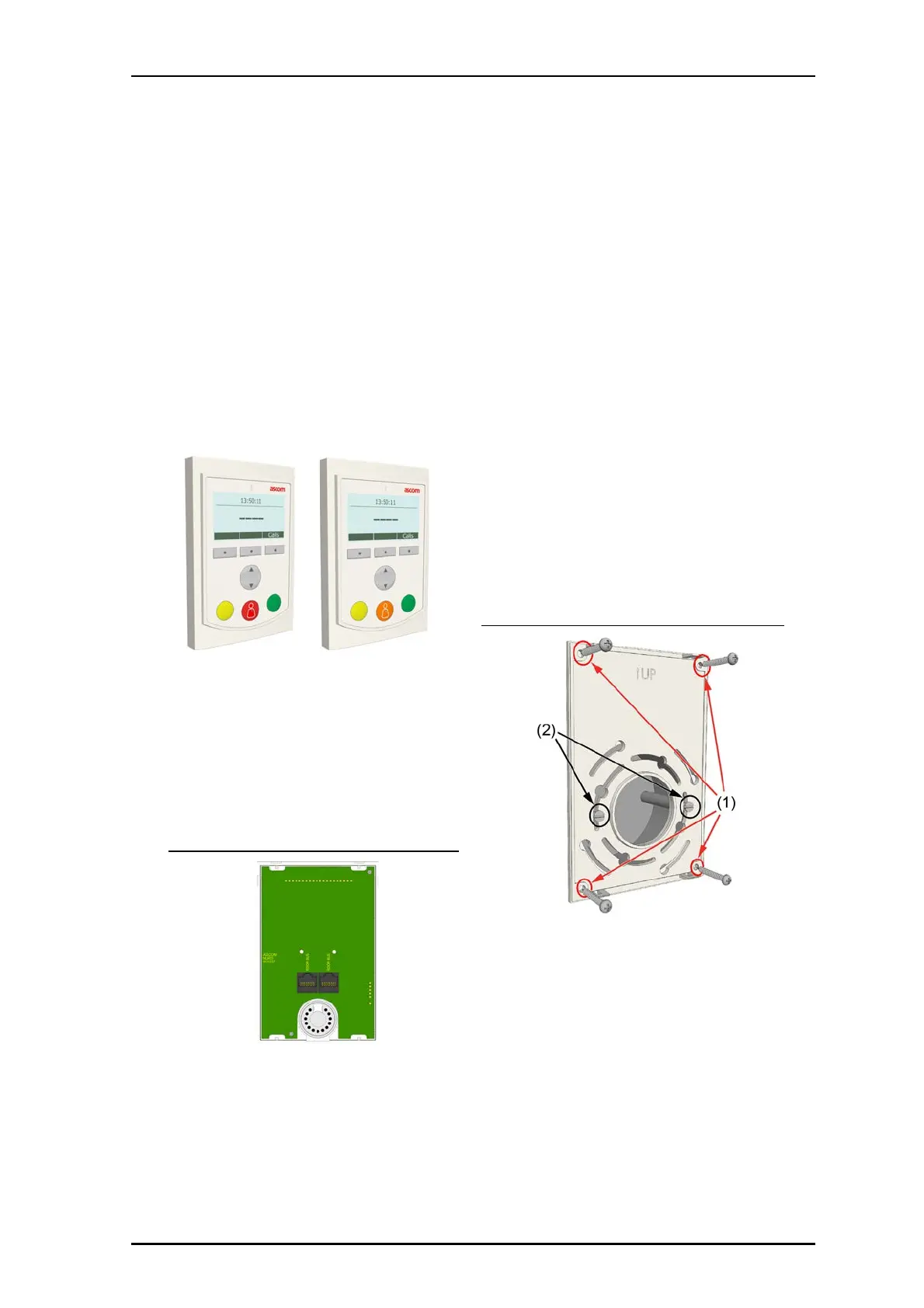
NURD Room Display (Rear)
NURD-HE (EU Market) NURD-HK (UK Market)
Installation
Note: Before beginning the installation, ensure all the
necessary cables are available and are properly terminated.
RJ-45 connectors should be terminated in accordance with
the T568B or EIA 568B connection standard.
A backplate for mounting is available for the Room Display.
To mount the backplate on a backbox:
1. Loosen the screws (item 2 in the figure below) so that
approximately 5mm (.20in.) extend from the backbox.
Backplate with mounting holes
Legend
(1) Optional
(2) Required
2. Pull the cables from the backbox through the backplate
hole.