P/N PM000223A • Rev. 1 • ISS 9 August 2017 70
Installation Manual
NU-Series Hardware
Room Modules
7.3.4 Television Interface Module Electrical Connections
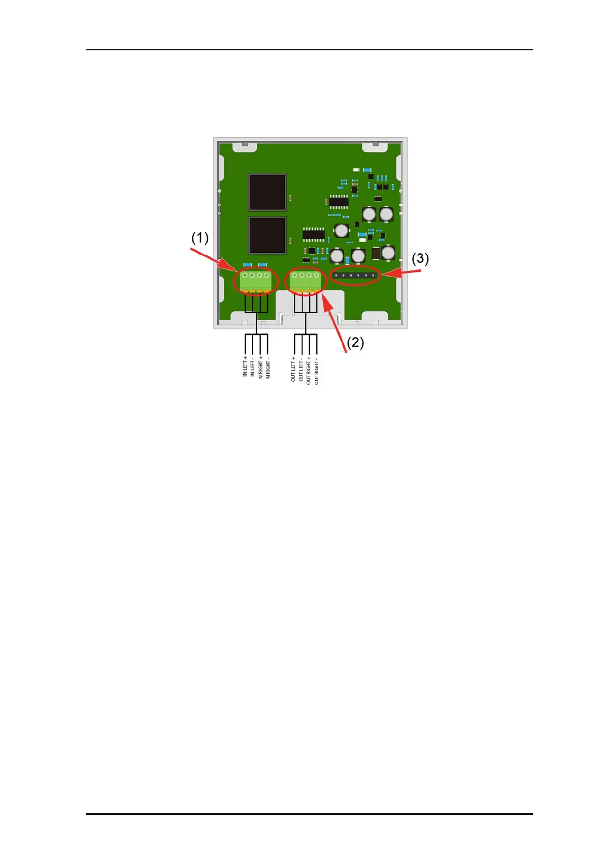
Figure 48 Television interface module connections
Legend:
(1) 4-pole television interface terminal to TV
(2) 4-pole auxiliary terminal to NUBM3X
(3) 6-pole terminal (not used)
To connect the Television Interface module:
1. Mount the module’s adapter to the backbox, close to the TV.
2. Slide the cables with their connectors through a module frame.
3. Mount an audio cable with a 4-pole connector to the 4-pin terminal (J1) on the
Television Interface module, and then attach the other end to the headphone jack
socket on the television.
4. Mount one end of a Cat5/5e/6/7 U/UTP cable terminated with 4-poll connectors to the
4-pin terminal (J2) on the Television Interface module, and then mount the other end
to the 4-pin terminal on the Bedside Extension module. See “NUBM3X Bedside
Extension Module” on page 76.
5. Place the lower edge of the module onto the two lower snap fasteners of the spacer.
6. Push the top edge of the module onto the two upper snap fasteners until the module
clicks onto the spacer.
Note: The 4-pole connector terminals are sold separately.