P/N PM000115A • Rev. 1.00 • ISS 01MAY2017
ascom
1 of 4
© 2017 Ascom, Inc.
NUPBC-H Passive Bus Concentrator
Installation Sheet
Description
The NUPBC-H Passive Bus Concentrator resides on the
hallway bus. The Passive Bus Concentrator covered in this
installation sheet is:
• NUPBC-H Passive Bus Concentrator
This device is mounted using the required backplate
provided to either a backbox or a wall.
The Passive Bus Concentrator is wall-mounted using the
supplied wall-mounted spacer.
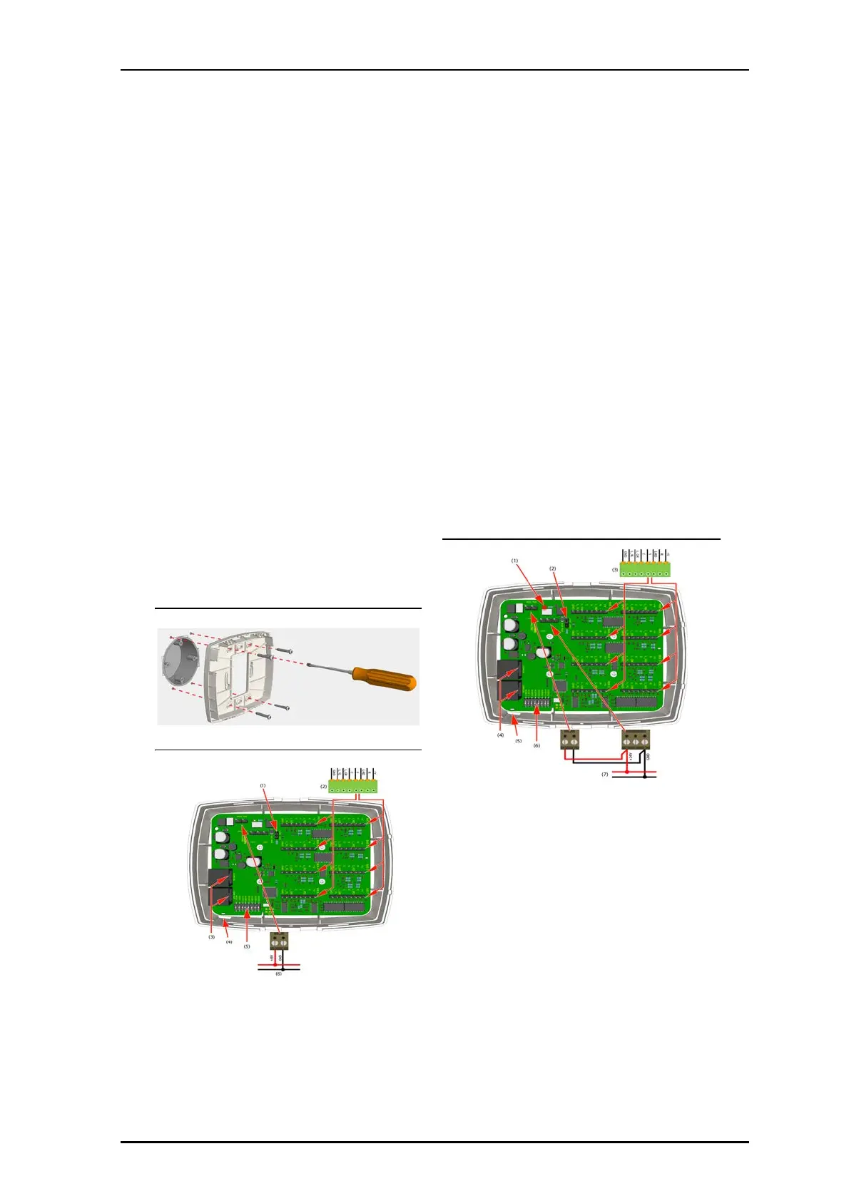
Mounting the Backplate Spacer
1. Mount the backplate spacer to the backbox and route
the wiring through the opening in the back.
Backplate Spacer Mounting
Circuit Board 36VDC
Legend
(1) Jumper set to +5V5 for NU-series passive modules
(2) Passive buses (0-7) for connecting NU-series passive
modules
(3) Hallway bus (2x RJ45)
(4) Status LED
(5) Address selection DIP switches
(6) Hallway power supply (36VDC)
Circuit Board 24VDC (teleCARE M Devices)
Legend
(1) 24VDC Power indicator LED
(2) Jumper set to +24VDC for legacy passive modules
(3) Passive buses (0-7) for connecting passive legacy
teleCARE M modules
(4) Hallway bus (2x RJ45)
(5) Status LED
(6) Address selection DIP switches
(7) +24VDC (teleCARE M) power supply
Warning: If 24VDC is applied while 5.5V bus peripherals are
on the bus, damage to the peripherals will result.