P/N PM000223A • Rev. 1 • ISS 9 August 2017 18
Installation Manual
NU-Series Hardware
System Cabling
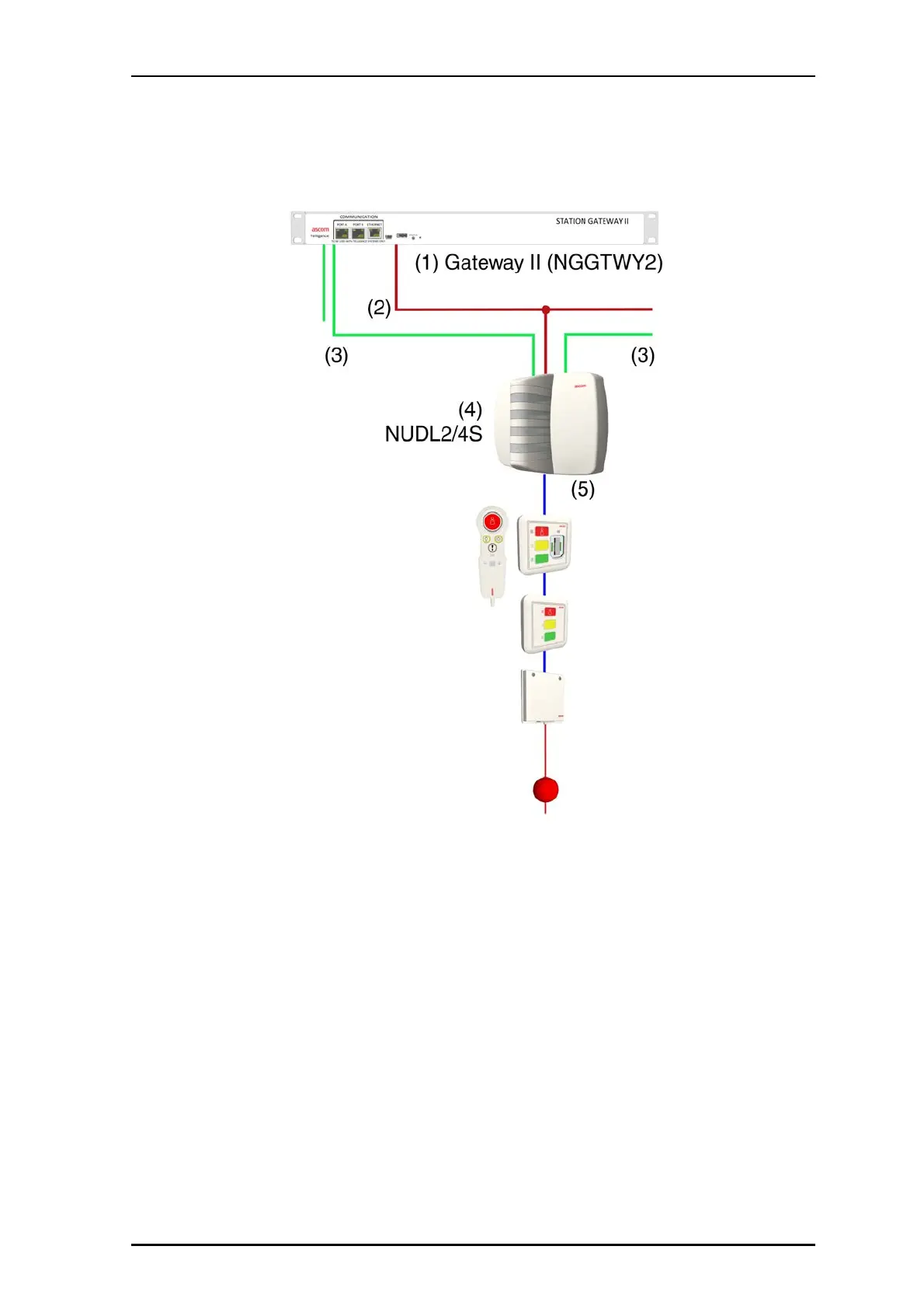
A typical active room bus setup is shown below.
Figure 16 Dome light with active room bus
Legend:
(1) Gateway II
(2) Power from Gateway II to hallway devices (+36V and GND)
(3) Hallway bus from Gateway II to hallway devices, See “Daisy Chaining Hallway
Devices” on page 16.
(4) Dome light (NUDL4S or NUDL2S)
(5) Two active room bus connectors
2.6.1 Active Bus Connections
The active room bus consists of four unshielded twisted wire pairs that carry +5.5V,
microphone, speaker, and ground. The bus uses a serial protocol with a a baud rate of
19k2. The room bus is daisy chained from module to module. All modules are equipped
with two RJ-45 connectors for easy daisy chaining.
Important: The room bus cable shall not exceed a maximum length of 30m(100ft).