P/N PM000158A • Rev. 1.0 • ISS 12JUNE2017
ascom
1 of 3
© 2017 Ascom, Inc.
NUMI2-HE External Input Module
Installation Sheet
Description
The NUMI2-HE External Input Module is designed to reside
on the active room bus. The NUMI2-HE has two Ascom
SafeConnect sockets on the front face and two RGB LEDs
(one above each socket).
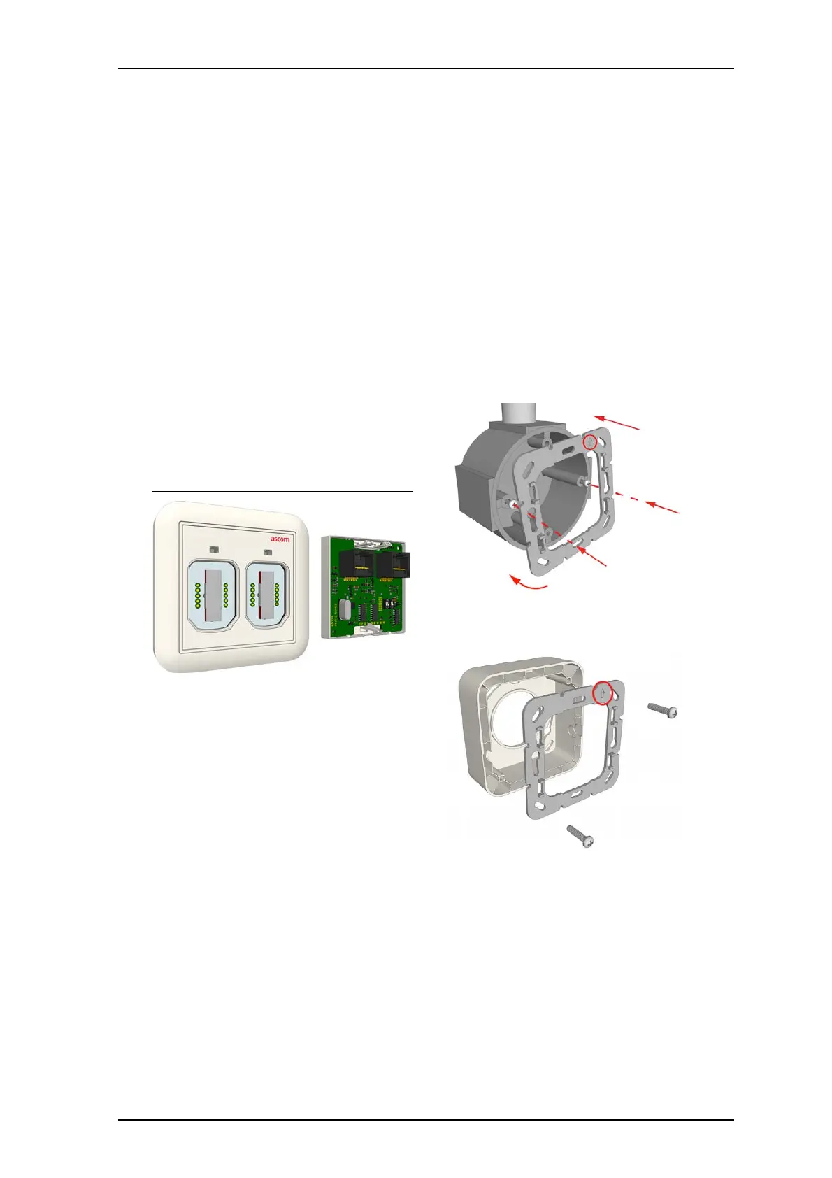
NUMI2-HE External Input Module (Front and Back)
Installation
Note: Before beginning the installation, ensure all
the necessary cables are available and are properly
terminated. RJ-45 connectors should be terminated
in accordance with the T568B or EIA 568B
connection standard.
The module can mount to a backbox, or to a wall by using
a surface-mounting spacer (NUSP1-HE).
To mount the module on a backbox or spacer:
1. When using a backbox, loosen the screws on the
backbox so that approximately 5mm extend out from
the backbox and the heads of the screws can pass
though the key-hole slots of the adapter plate.
When using a spacer, ensure the spacer is properly
mounted to the wall and that the adapter screws are
available.
2. Place the adapter (with the arrow facing up) over the
backbox or spacer and ensure that it is level.
3. Tighten the screws.
4. Pull the cables from the backbox or spacer though the
adapter.