4 of 4
P/N PM000160A • Rev. 1.00 • ISS 24APR2017
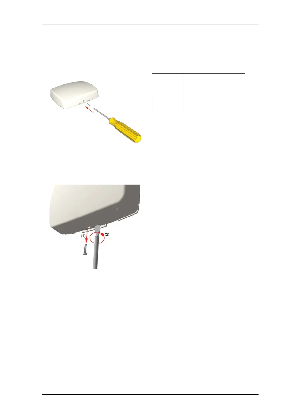
4. Insert the locking screw into the bottom of the NUIOM-H,
and then tighten the screw until it is snug, as shown
below. Do not over tighten.
Removal
Follow the steps below to remove the NUIOM-H from the
backplate.
Note: Failure to follow the proper removal procedure may
result in damage to the module.
1. Remove the locking screw from the bottom of the NUIOM-
H. See item 1 in the figure below.
2. Insert a 6mm flat-blade screwdriver into the notch at the
bottom of the NUIOM-H, and then apply light upward
pressure. See item 2 in the figure above.
3. Gently twist screwdriver to disengage the NUIOM-H from
the backplate. Do not use excessive force when twisting.
4. Remove the NUIOM-H from backplate.
Specifications
f
Wire/terminations
Cat 5/5e/6/7, U/UTP
NOTE: Cat 6/7 cable will work
electrically but may be too stiff for
some back boxes.
4 pole connector
Compatible back
boxes
European Union, United Kingdom:
Standard plastic or metal back box
with mounting holes 60mm (2.36in.)