P/N PM000223A • Rev. 1 • ISS 9 August 2017 7
Installation Manual
NU-Series Hardware
Introduction
1.4.5 Passive Room Bus
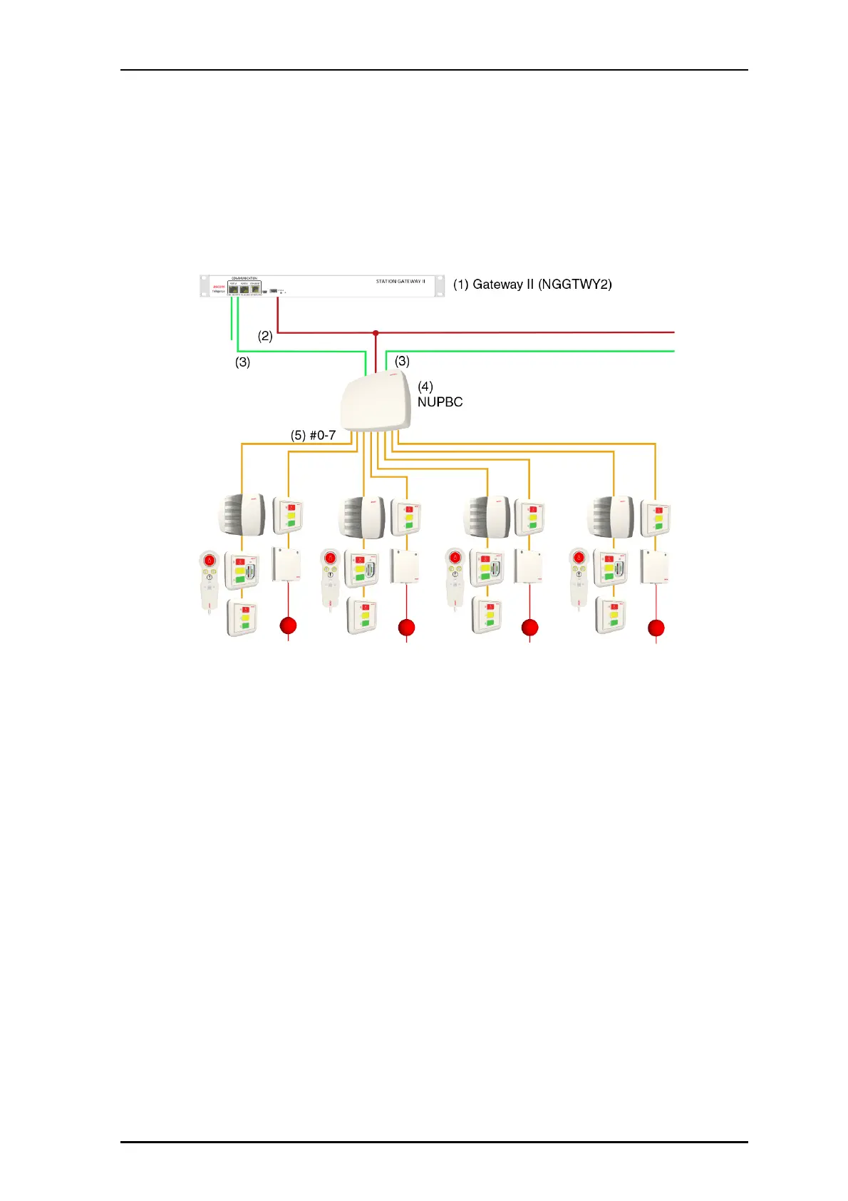
The Passive Bus Concentrator (NUPBC) resides on the hallway bus and controls the passive
room bus and is the interface between the Gateway II and the passive modules. The
NUPBC distributes power and communication to the attached modules through its eight
passive room buses. The following figure shows a system setup with an NUPBC.
Figure 5 Passive room bus with a NUPBC and passive room modules
Legend:
(1) Gateway II
(2) Power from Gateway II to hallway devices and room modules (36VDC)
(3) Hallway bus
(4) NUPBC Passive Bus Concentrator
(5) Passive room bus
Note: The Telligence system is an electrically supervised system, except for the
passive devices connected to the passive room buses.
Each NUPBC includes eight passive bus terminals, two RJ-45 receptacles for connecting to
the hallway bus network, six DIP switches for setting its hallway bus address, and a blue
status LED. The LED illuminates when power is applied to the concentrator and flashes
when the NUPBC is in fault.
1.4.6 IP Bus
The IP bus is controlled by a Power over Ethernet (PoE) switch. The IP devices, including the
Touch Screen Display (NGTDSP and NGWDSP), the Corridor Display (NUCD12IP), Telligence
Bridge computer, and Innovaphone VoIP Gatway are PoE-capable, reside on the IP bus,
and are powered by the PoE switch. The Telligence Bridge computer is powered separately.