P/N PM000160A • Rev. 1.00 • ISS 24APR2017
3 of 4
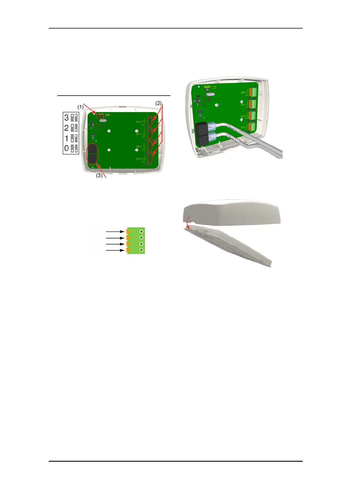
The following figure shows the DIP switches and cable
connections on the back of NUIOM-H module.
NUIOM-H module connections
Legend
(1) DIP switches for bus addressing
(2) 4x 4-pole I/O connection to auxiliary devices
(3) 2x RJ-45 connections to the room bus
To terminate a 4-pole connector for an I/O cable:
1. Terminate the I/O cable with a 4-pole block connector, as
shown below.
2. Terminate the other end of the cable as needed for that
auxiliary device.
To connect a NUIOM-H IO module:
1. Set the IO module’s DIP switches according to your
installation’s bus addressing scheme. See the figure
NUIOM-H module connections, item 1.
Note: If your installation does not use the DIP switches, set
the DIP switches to the 0 position and use the Software
Configuration Tool.
2. Attach the 4-pole connectors from the auxiliary devices to
the 4-pin terminal. Ensure the connector is seated properly
on the terminal pins. See the figure NUIOM-H module
connections, item 2.
3. Insert the RJ-45 connector (from the room bus) into a jack
on the back of the module, and then insert the next RJ-45
connector (to the next module) into the other jack. See the
figure NUIOM-H module connections, item 3.
IN
GND
COM
RELAY
To mount the module to the backplate:
1. Ensure that all cable connections are properly secured to
the jacks and terminals on the back of the NUIOM-H.
2. Place the module on to the two top fasteners on the
backplate.
3. Press the module firmly against the backplate so that the
bottom fasteners of the NUIOM-H snap closed on the
backplate.