2 of 4
P/N PM000160A • Rev. 1.00 • ISS 24APR2017
Mounting the Backplate Spacer Without a Backbox
When no backbox is available, you can mount the NUIOM-H
directly to a flat surface using four screws suitable for the
wall type. Cable wires should enter and leave the module’s
housing through the hole in the center of the backplate
spacer, or through the knockouts in the top and sides of the
backplate spacer.
Do not distort or twist the backplate spacer when mounting
it to a wall. If the backplate spacer is distorted, the module
will not fit properly and may fall off. To prevent distortion,
only mount the backplate spacer on a smooth and level
surface. Do not over-tighten the screws.
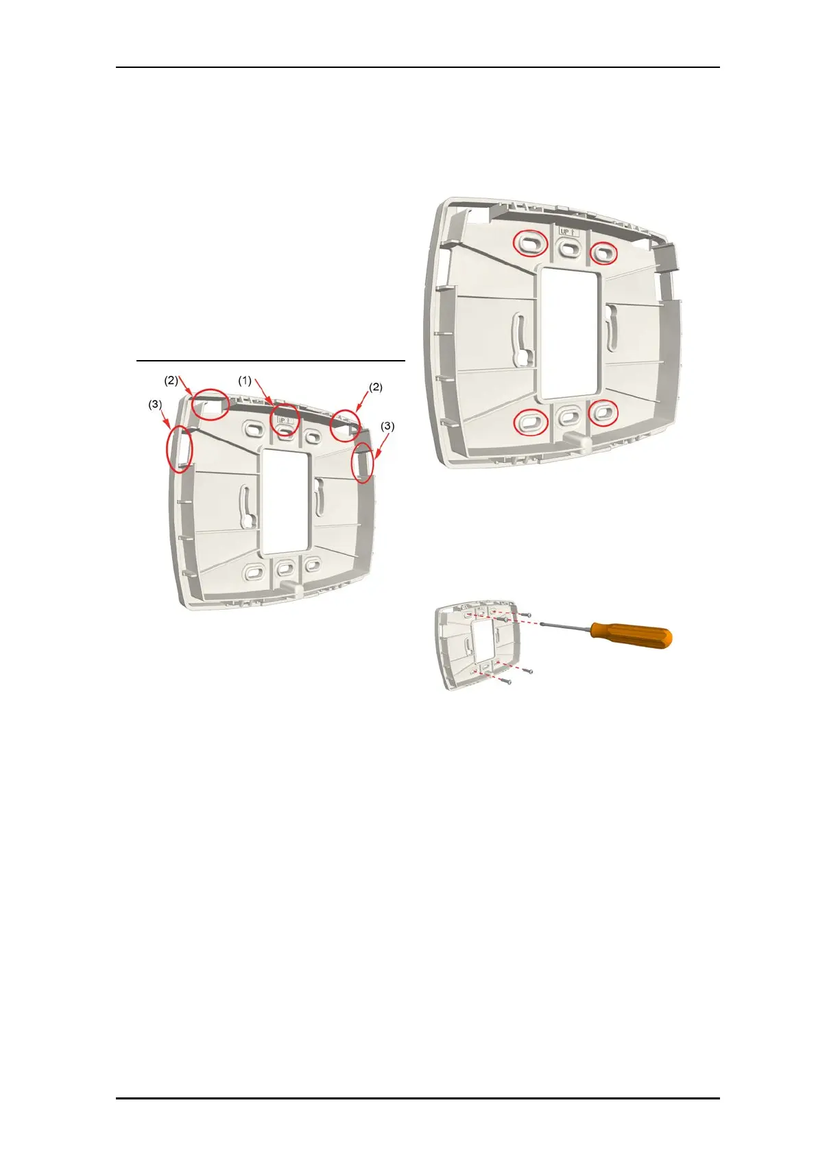
Backplate spacer with directional arrow and knockouts
Legend
(1) Directional arrow indicator
(2) Top knockouts
(3) Side knockouts
To remove the knockouts:
1. Determine how much space will be needed to
accommodate the cables entering the I/O module’s
housing, and then choose which knockouts to remove.
2. Locate the knockouts to be removed from the top or sides
of the backplate spacer. See the figure above, items 2 and
3.
3. Using a cutter or pliers, carefully remove the excess plastic
from the knockouts.
To mount the backplate spacer on a wall:
1. Place the backplate spacer against a flat wall and orient it
so that the arrow (printed on the inside of the backplate
spacer) is pointing up and that the backplate spacer is
level. Use a leveling device to check, if necessary.
2. Using the backplate spacer as a template, mark four
holes for the screws using the fitting holes located in the
backplate spacer as shown in the previous image.
3. Remove the backplate spacer and drill holes for the
screws that will be used, such as wood, concrete, or
drywall screws, or screws with anchors.
4. Place the backplate spacer over the holes, insert the
screws, and then tighten.
5. If the cables come through the wall, pull the cables
through the hole in the center of the backplate spacer.
-or-
If the cables come through a channel, align the cables
through the knockouts at the top and sides of the
backplate spacer.
Setting DIP Switches and Connecting Cables
The NUIOM-H provides RJ-45 jacks for connecting to the
room bus, and DIP switches for setting its room bus
address. It also includes four I/O connectors for sending
and receiving contact closure information from auxiliary
devices.