2 of 4
P/N PM000115A • Rev. 1.00 • ISS 01MAY2017
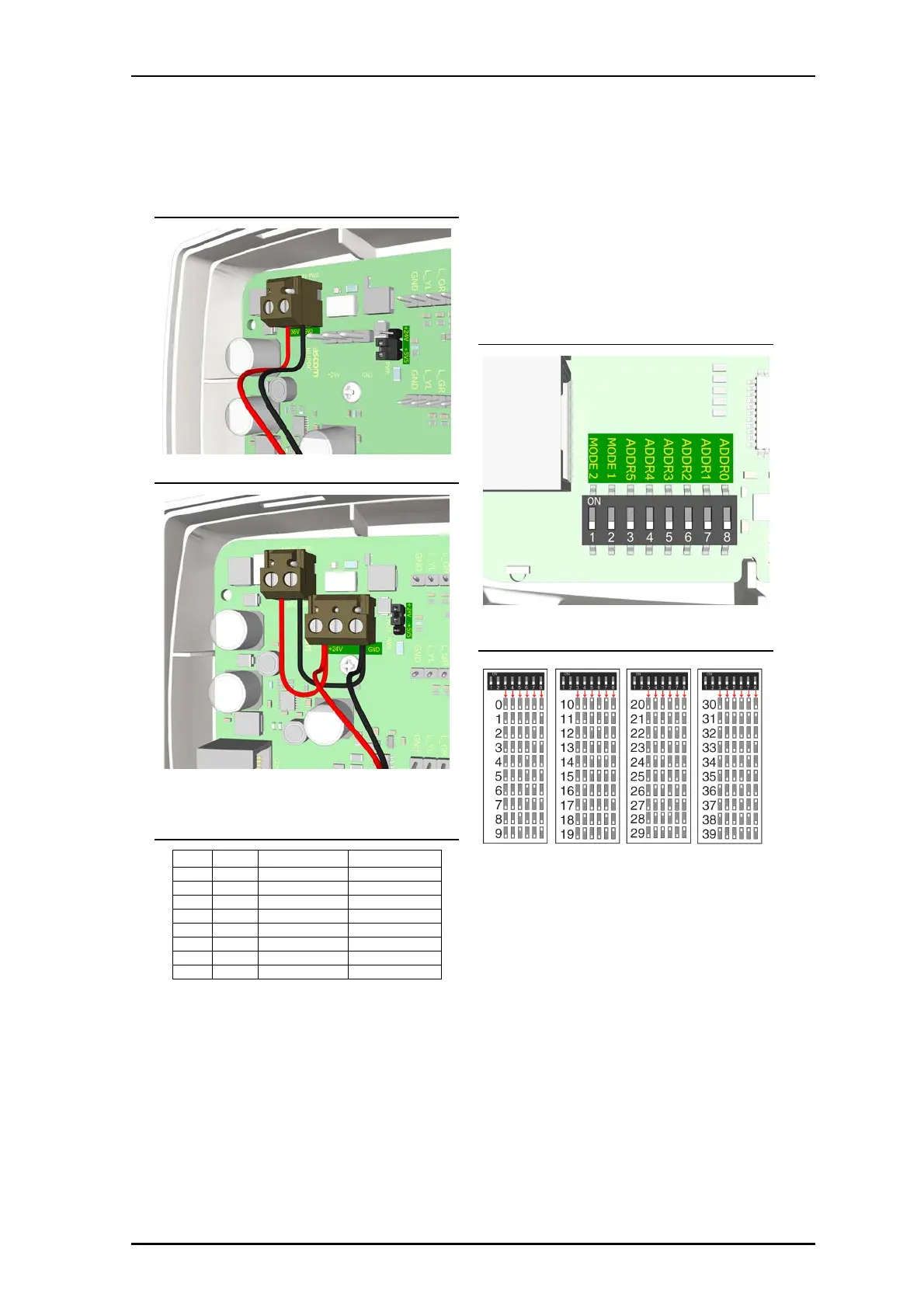
NUPBC Power Connections 36VDC
NUPBC Power Connections 24VDC (teleCARE M devices)
The red LED on the board will illuminate when in 24VDC
mode.
8-Pole Passive Bus Connection Pinouts
Pin # Pin Description Color
1 +V Positive power Orange/White
2R Reset Orange
3 L_RD LED Red Blue/White
4S Set Blue
5 C C-line Green/White
6 L_GR LED Green Green
7 L_YL LED Yellow Brown/White
8 GND Ground Brown
DIP Switch Addressing
The PBC will come from the package with the DIP Switch
settings all at zero. A new address will need to be assigned
for each device. Use a small slotted screwdriver or similar
tool to assign the addresses or keep all DIP switches in the
OFF position and use the Configuration Tool and serial
number of the device for identification.
DIP Switch - 8 Position
DIP Switch Address Table
2. Daisy chain hallway bus with RJ-45 connectors to the
Passive Bus Concentrator into the jacks.