P/N PM000115A • Rev. 1.00 • ISS 01MAY2017
3 of 4
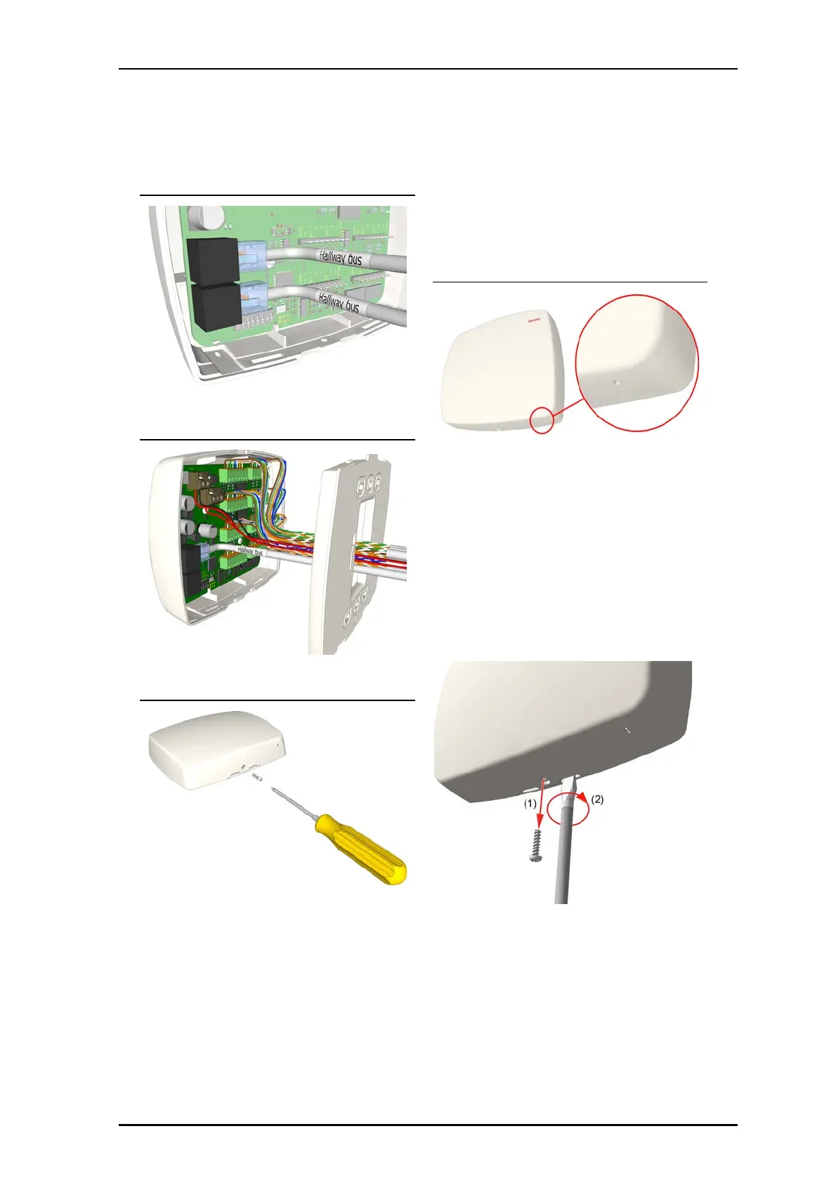
RJ-45 Jacks Connection
3. Attach the device to the backplate by aligning to frame
and pushing into place until a snap is heard.
Completed Wiring Detail
4. Install screw to bottom of cover.
Cover Screw
LED Status Indicator
The Passive Bus Concentrator is equipped with a status LED
indicator located at the bottom of the front cover which will
illuminate blue when operating correctly. The LED will flash if
there is a steady issue with the device.
Status LED
Removal
The following provides the proper steps for removal of the
Passive Bus Concentrator.
Note: Failure to follow the proper removal procedure may
result in damage to the device.
1. Remove cover screw from bottom of device. See Item 1 in
following graphic.
2. Insert a 6mm flat blade screwdriver into the notch at the
bottom of the device and apply light upward pressure.
3. Gently twist screwdriver to disengage device from
backplate. Do not use excessive force while twisting. See
Item 2 in following graphic.
4. Remove device from backplate.