on the inside of the lower edge of the cover plate (1). See
graphic below.
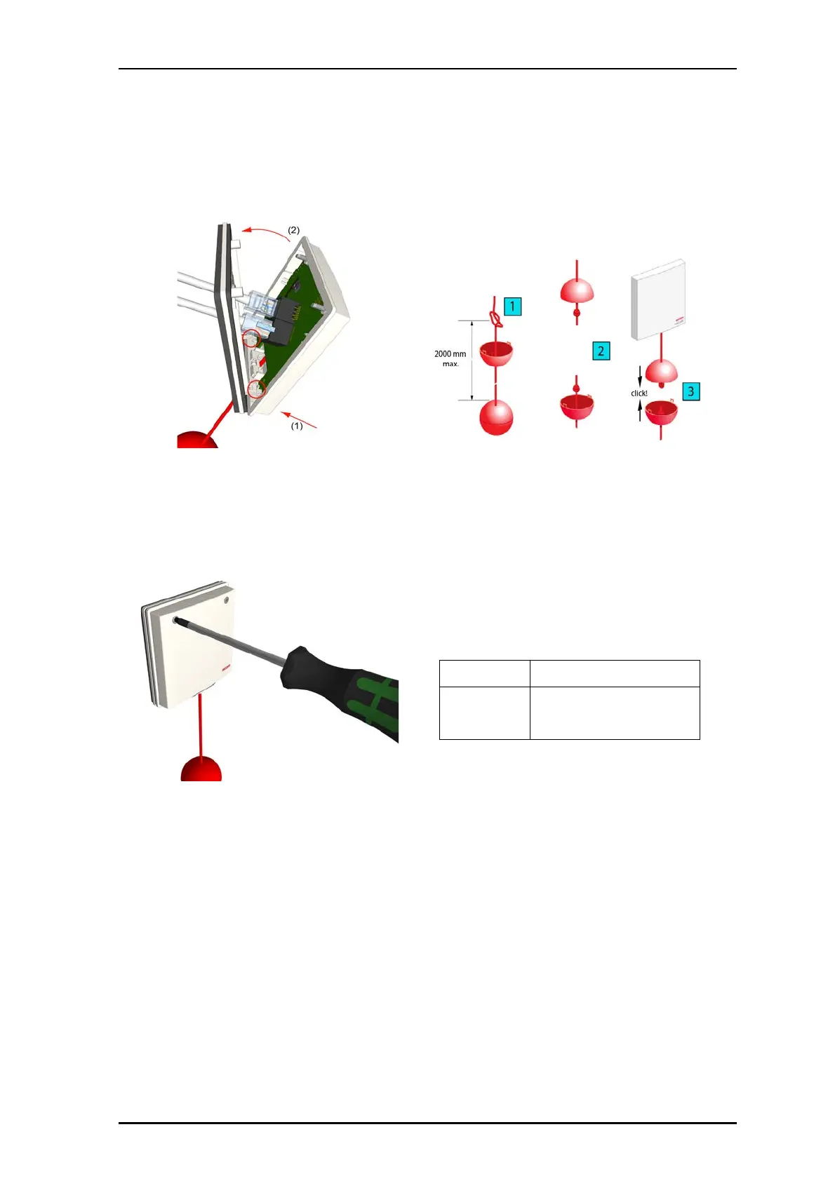
5. Rotate the pull cord module up to the backplate (item 2)
so that the screws line up with the fixing posts on the
backplate. See graphic above.
6. Press the pull cord module on to the backplate ensuring
that the latch fasteners stay engaged. Carefully tighten
the two screws. The screws should be tightened to apply
just enough pressure on the gasket to compress it evenly
around and between the cover plate and the backplate.
Important: Do not excessively tighten the T
10 Torx screws as
this will distort the cover plate and the foam gasket resulting
in an ineffective waterproof seal.
Assembling and Attaching the Pull Cord
The pull cord assembly includes the two meter pull cord and
two plastic balls. The top ball is a breakaway ball that
separates when the cord is pulled with excessive force. The
second ball (lower ball) weights the pull cord and allows the
cord to be grabbed easily.
The upper half of the pull cord comes already attached to the
pull cord module. The lower half of the cord can be connected
to the upper half by clicking the two halves of the breakaway
ball. See Figure Below.
Steps to Assemble and Attach the Pull Cord
To attach the pull cord assembly:
1. Ensure that the pull cord module is properly mounted to
the wall and that all cable connects have been made.
2. Adjust the length of the cord by pulling the cord
though the hole in the bottom half of the breakaway
ball, and then retying the knot in the cord. See
Previous Figure, item 1.
3. Align the two halves of the breakaway ball so that
the edges are touching, and then press them until they
click together. See Previous Figure, items 2 and 3.
4. Extend the cord to it’s full length, and then allow it
to hang freely from the pull cord module.
Specifications
Wire/terminations
Cat 5/5e/6/7 U/UTP with RJ-45
connectors.
Compatible
electrical boxes
European Union, United Kingdom:
Standard plastic or metal back box
with mounting holes: 60mm
(2.36in.),